Common Rail -- Installation |
| 1. INSTALL COMMON RAIL ASSEMBLY |
- NOTICE:
- In cases where the common rail is replaced, the fuel inlet pipe and injection pipe must also be replaced.
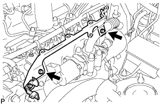
Temporarily install the common rail assembly with the 2 bolts.
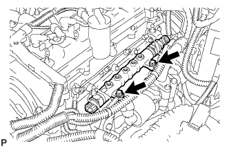 |
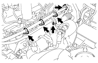
Temporarily install the 2 fuel inlet pipes.
 |
Temporarily install the No. 1, No. 2, No. 3 and No. 4 injection pipes.
Tighten the common rail assembly with the 2 bolts.
- Torque:
- 21 N*m{210 kgf*cm, 15 ft.*lbf}
Remove the No. 1, No. 2, No. 3 and No. 4 injection pipes.
Remove the 2 fuel inlet pipes.
Connect the pressure discharge valve connector (*1).
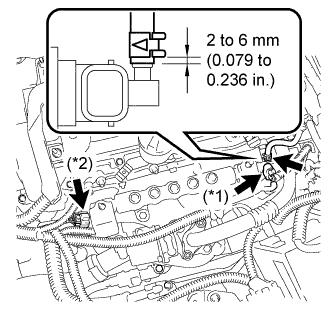 |
Connect the fuel pressure sensor connector (*2).
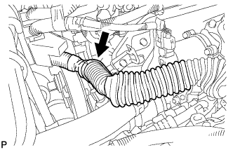
Using pliers, slide the clip to connect the fuel hose as shown in the illustration.
| 2. INSTALL FUEL INLET PIPE SUB-ASSEMBLY |
- NOTICE:
- In cases where the common rail is replaced, the fuel inlet pipe must also be replaced.
- HINT:
| 3. CONNECT ENGINE WIRE |
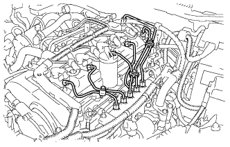
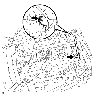
Install the engine wire harness to the cylinder head cover.
 |
Connect the 2 harness clamps and the 4 injector connectors.
Install the 2 nuts.
- Torque:
- 2.2 N*m{22 kgf*cm, 19 in.*lbf}
| 4. INSTALL NO. 4 INJECTION PIPE SUB-ASSEMBLY |
- NOTICE:
- In cases where the common rail is replaced, the injection pipes must also be replaced.
- HINT:
| 5. INSTALL NO. 3 INJECTION PIPE SUB-ASSEMBLY |
- HINT:
| 6. INSTALL NO. 2 INJECTION PIPE SUB-ASSEMBLY |
- HINT:
- Perform the same procedure as for the No. 3 injection pipe.
| 7. INSTALL NO. 1 INJECTION PIPE SUB-ASSEMBLY |
- HINT:
- Perform the same procedure as for the No. 3 injection pipe.
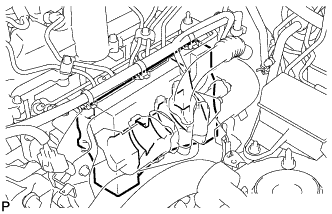
Tighten the 4 injection pipe clamps with the 2 bolts.
- Torque:
- 5.0 N*m{51 kgf*cm, 44 in.*lbf}
| 8. INSTALL NO. 1 INTAKE MANIFOLD INSULATOR |
Install the No. 1 intake manifold insulator.
 |
| 9. INSTALL WIRING HARNESS CLAMP BRACKET |
Install the wire harness clamp bracket with the 2 bolts.
 |
Connect the 5 wire harness clamps.
 |
Connect the wire harness clamp.
 |
| 10. INSTALL NO. 1 FUEL PIPE |
Install the No. 1 fuel pipe with the 2 bolts.
 |
Connect the 2 fuel hoses and 2 clips.
| 11. CONNECT CABLE TO NEGATIVE BATTERY TERMINAL |
| 12. CHECK FOR FUEL LEAKS |
PERFORM ACTIVE TEST
Connect the intelligent tester to the DLC3.
Turn the engine switch ON (IG).
Turn the intelligent tester ON.
Enter the following menus: Powertrain / ENGINE / Active Test.
Perform the Active Test.
Intelligent Tester Display Test Details Control Range Diagnostic Notes Test the Fuel Leak Pressurize common rail internal fuel pressure, and check for fuel leaks Stop/Start - Fuel pressure inside common rail pressurized to specified value and engine speed increased to 2,000 rpm when "Start" is selected
- Above conditions to be maintained while "Start" is selected
- Fuel pressure inside common rail pressurized to specified value and engine speed increased to 2,000 rpm when "Start" is selected
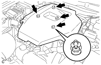
| 13. INSTALL NO. 1 ENGINE COVER |
Install the No. 1 engine cover.
 |
| 14. PERFORM INITIALIZATION |
Perform initialization procedure (Click here).
- HINT:
- Some vehicle systems require initialization after reconnecting the negative battery terminal.