Land Cruiser URJ200 URJ202 GRJ200 VDJ200 - 1UR-FE COOLING
COOLANT - REPLACEMENT
| 1. REMOVE FRONT FENDER SPLASH SHIELD SUB-ASSEMBLY LH |
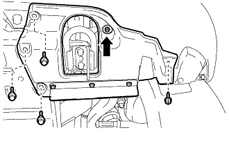
Remove the 3 bolts and screw.
Turn the clip indicated by the arrow in the illustration to remove the front fender splash shield sub-assembly LH.
| 2. REMOVE FRONT FENDER SPLASH SHIELD SUB-ASSEMBLY RH |
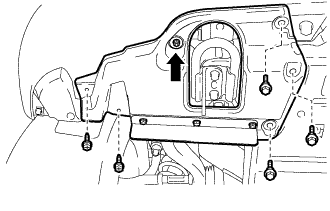
Remove the 3 bolts and 2 screws.
Turn the clip indicated by the arrow in the illustration to remove the front fender splash shield sub-assembly RH.
| 3. REMOVE NO. 1 ENGINE UNDER COVER SUB-ASSEMBLY |
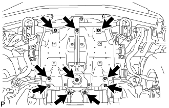
Remove the 10 bolts and No. 1 engine under cover sub-assembly.
| 4. DRAIN ENGINE COOLANT |
- CAUTION:
- Do not remove the radiator cap while the engine and radiator are still hot. Pressurized, hot engine coolant and steam may be released and cause serious burns.
Loosen the radiator drain cock plug.
Remove the radiator cap and drain the coolant.
- HINT:
- Collect the coolant in a container and dispose of it according to the regulations in your area.
Loosen the 2 cylinder block drain cock plugs and drain the coolant from the engine.
Tighten the 2 cylinder block drain cock plugs.
- Torque:
- 13 N*m{ 130 kgf*cm, 9 ft.*lbf}
Tighten the radiator drain cock plug by hand.
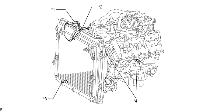
| *1 | Reservoir Cap | *2 | Radiator Cap |
| *3 | Radiator Drain Cock Plug | *4 | Cylinder Block Drain Cock Plug |
| 5. ADD ENGINE COOLANT |
Add engine coolant.
- Standard Capacity (w/o ATF Warmer):
Item Specified Condition w/ Rear Heater 16.5 liters (17.4 US qts, 14.5 Imp. qts) w/o Rear Heater 13.8 liters (14.6 US qts, 12.1 Imp. qts)
- Standard Capacity (w/ ATF Warmer):
Item Specified Condition w/ Rear Heater 17.0 liters (18.0 US qts, 15.0 Imp. qts) w/o Rear Heater 14.2 liters (15.0 US qts, 12.5 Imp. qts)
- NOTICE:
- Do not substitute plain water for engine coolant.
- HINT:
Slowly pour coolant into the radiator reservoir until it reaches the F line.
Install the reservoir cap.
Install the radiator cap.*1
Start the engine and stop it immediately.*2
Allow approximately 10 seconds to pass. Then remove the radiator cap and check the coolant level. If the coolant level has decreased, add coolant.*3
Repeat steps *1, *2 and *3 until the coolant level does not decrease.
- HINT:
- Be sure to perform this step while the engine is cold, as air in the No. 1 radiator hose will flow into the radiator if the engine is warmed up and the thermostat opens.
Install the radiator cap.*4
Set the air conditioning as follows.*5
| Item | Condition |
| Fan speed | Any setting except off |
| Temperature | Toward WARM |
| Air conditioning switch | Off |
Start the engine, warm it up until the thermostat opens, and then continue to run the engine for several minutes to circulate the coolant.*6
- CAUTION:
- NOTICE:
- HINT:
Stop the engine, wait until the engine coolant cools down to ambient temperature. Then remove the radiator cap and check the coolant level.*7
- CAUTION:
- Do not remove the radiator cap while the engine and radiator are still hot. Pressurized, hot engine coolant and steam may be released and cause serious burns.
If the coolant level has decreased, add coolant and warm up the engine until the thermostat opens.*8
If the coolant level has not decreased, check that the coolant level in the radiator reservoir is at the F line.
If the coolant level is below the F line, repeat steps *4 through *8.
If the coolant level is above the F line, drain coolant until the coolant level reaches the F line.
| 6. INSPECT FOR COOLANT LEAK |
- CAUTION:
- To avoid being burned, do not remove the radiator reservoir cap while the engine and radiator are still hot. Thermal expansion may cause hot engine coolant and steam to blow out from the radiator.
Remove the radiator cap.
Check for excessive deposits of rust or scales around the radiator reservoir cap and radiator reservoir filler hole. Also, the engine coolant should be free of oil.
If excessively dirty, replace the engine coolant.
Install the radiator cap.
| 7. INSTALL NO. 1 ENGINE UNDER COVER SUB-ASSEMBLY |
Install the No. 1 engine under cover sub-assembly with the 10 bolts.
- Torque:
- 29 N*m{ 296 kgf*cm, 21 ft.*lbf}
| 8. INSTALL FRONT FENDER SPLASH SHIELD SUB-ASSEMBLY LH |
Push in the clip to install the front fender splash shield sub-assembly LH.
Install the 3 bolts and screw.
| 9. INSTALL FRONT FENDER SPLASH SHIELD SUB-ASSEMBLY RH |
Push in the clip to install the front fender splash shield sub-assembly RH.
Install the 3 bolts and 2 screws.