Ecd System Ecm Power Source Circuit
Engine. Lexus Is250, Is220D. Gse20 Ale20
DESCRIPTION
WIRING DIAGRAM
INSPECTION PROCEDURE
CHECK HARNESS AND CONNECTOR (ECM - BODY GROUND)
CHECK ECM TERMINAL VOLTAGE (IGSW TERMINAL)
INSPECT FUSE (IGN FUSE)
CHECK TERMINAL VOLTAGE (EFI MAIN RELAY TERMINAL)
INSPECT FUSE (ECD FUSE)
INSPECT EFI MAIN RELAY
CHECK HARNESS AND CONNECTOR (MAIN RELAY - ECM)
ECD SYSTEM - ECM Power Source Circuit |
DESCRIPTION
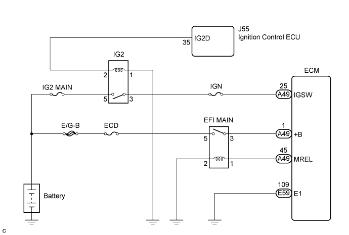
When the engine switch is turned ON (IG), the battery voltage is applied to terminal IGSW of the ECM. The ECM "MREL" output signal causes a current to flow to the coil, closing the contacts of the MAIN relay and supplying power to terminal +B of the ECM.
WIRING DIAGRAM
INSPECTION PROCEDURE
- NOTICE:
- After replacing the ECM, the new ECM needs registration (Click here) and initialization (Click here).
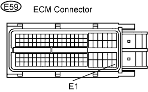
| 1.CHECK HARNESS AND CONNECTOR (ECM - BODY GROUND) |
Disconnect the E59 ECM connector.
Measure the resistance of the wire harness side connector.
- Standard resistance:
Tester Connection
| Specified Condition
|
E1 (E59-109) - Body ground
| Below 1 Ω
|
| | REPAIR OR REPLACE HARNESS OR CONNECTOR |
|
|
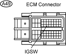
| 2.CHECK ECM TERMINAL VOLTAGE (IGSW TERMINAL) |
Disconnect the A49 ECM connector.
Turn the engine switch ON (IG).
Measure the voltage of the ECM connectors.
- Standard voltage:
Tester Connection
| Specified Condition
|
IGSW (A49-25) - Body ground
| 9 to 14 V
|
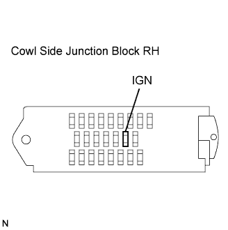
| 3.INSPECT FUSE (IGN FUSE) |
Remove the IGN fuse from the cowl side J/B LH.
Measure the resistance of the fuse.
- Standard resistance:
- Below 1 Ω
| OK |
|
|
|
| CHECK AND REPLACE SMART ACCESS SYSTEM WITH PUSH-BUTTON START |
|
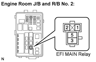
| 4.CHECK TERMINAL VOLTAGE (EFI MAIN RELAY TERMINAL) |
Remove the EFI MAIN relay from the engine room J/B and R/B No. 2.
Turn the engine switch ON (IG).
Measure the voltage.
- Standard voltage:
Tester Connection
| Specified Condition
|
EFI MAIN relay (1) - Body ground
| 9 to 14 V
|
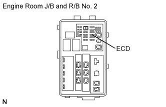
| 5.INSPECT FUSE (ECD FUSE) |
Remove the ECD fuse from the engine room J/B and R/B No. 2.
Measure the resistance of the fuse.
- Standard resistance:
- Below 1 Ω
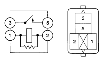
Remove the EFI MAIN relay from the engine room R/B No. 2.
Inspect the EFI MAIN relay.
- Standard resistance:
Tester Connection
| Specified Condition
|
3 - 5
| 10 kΩ or higher
|
Below 1 Ω
(Apply battery voltage to terminals 1 and 2)
|
Reinstall the EFI MAIN relay.
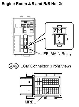
| 7.CHECK HARNESS AND CONNECTOR (MAIN RELAY - ECM) |
Check the harness and connector between the EFI MAIN relay and ECM.
Remove the EFI MAIN relay from the engine room J/B and R/B No. 2.
Disconnect the A49 ECM connector.
Check the resistance between the wire harness side connectors.
- Standard resistance (Check for open):
Tester Connection
| Specified Condition
|
EFI MAIN relay (1) - MREL (A49-45)
| Below 1 Ω
|
- Standard resistance (Check for short):
Tester Connection
| Specified Condition
|
EFI MAIN relay (1) or MREL (A49-45) - Body ground
| 10 kΩ or higher
|
Reconnect the ECM connector.
Check the harness and connector between the EFI MAIN relay and body ground.
Remove the EFI MAIN relay from the engine room J/B and R/B No. 2.
Check the resistance between the wire harness side connector and body ground.
- Standard resistance (Check for open):
Tester Connection
| Specified Condition
|
EFI MAIN relay (2) - Body ground
| Below 1 Ω
|
Reinstall the EFI MAIN relay.
| | REPAIR OR REPLACE HARNESS OR CONNECTOR (MAIN RELAY - ECM) |
|
|