Dtc B1280 Left Side Junction Block Ecu Communication Stop
DESCRIPTION
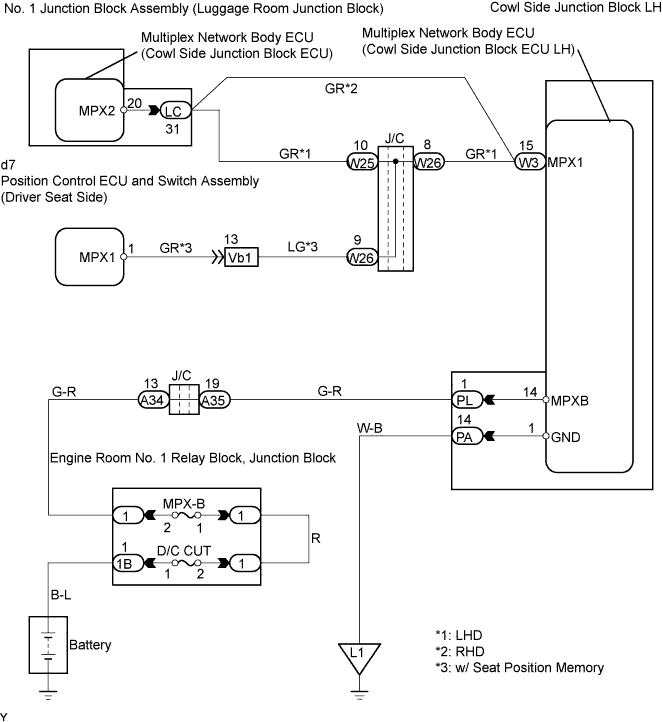
WIRING DIAGRAM
INSPECTION PROCEDURE
CHECK FUSE (MPX-B, D/C CUT)
CHECK WIRE HARNESS (COWL SIDE JUNCTION BLOCK LH - BATTERY AND BODY GROUND)
CHECK RESISTANCE OF COMMUNICATION LINE
DTC B1280 Left Side Junction Block ECU Communication Stop |
DESCRIPTION
This DTC is detected when communication between the multiplex network body ECU (cowl side junction block ECU LH) and network gateway ECU stops for more than 10 seconds.DTC No.
| DTC Detection Condition
| Trouble Area
|
B1280
| Cowl side junction block ECU LH communication stops
| - Multiplex network body ECU (cowl side junction block ECU LH)
- Wire harness
|
WIRING DIAGRAM
INSPECTION PROCEDURE
| 1.CHECK FUSE (MPX-B, D/C CUT) |
Remove the MPX-B from the engine room No. 1 relay block.
Measure the resistance of the fuses.
- Standard:
- Below 1 Ω
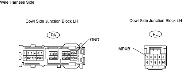
| 2.CHECK WIRE HARNESS (COWL SIDE JUNCTION BLOCK LH - BATTERY AND BODY GROUND) |
Disconnect the PL and PA J/B connectors.
Measure the resistance and voltage of the wire harness side connectors.
- Standard resistance:
Tester Connection
| Specified Condition
|
PA-14 (GND) - Body ground
| Below 1 Ω
|
- Standard voltage:
Tester Connection
| Specified Condition
|
PL-1 (MPXB) - Body ground
| 10 to 14 V
|
| | REPAIR OR REPLACE HARNESS AND CONNECTOR |
|
|
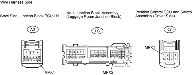
| 3.CHECK RESISTANCE OF COMMUNICATION LINE |
Disconnect the W3 ECU connector.
Disconnect the LC J/B connector.
Disconnect the d7 switch connector.
Measure the resistance of the wire harness side connectors.
- Standard resistance:
Tester Connection
| Specified Condition
|
W3-15 (MPX1) - LC-31 (MPX2)
| Below 1 Ω
|
W3-15 (MPX1) - d7-1 (MPX1)
| Below 1 Ω
|
- Result:
Result
| Proceed to
|
Both are OK
| A
|
One is OK
| B
|
Both are NG
| C
|
| | REPLACE COWL SIDE JUNCTION BLOCK LH AND HARNESS AND CONNECTOR |
|
|
| | REPAIR OR REPLACE HARNESS AND CONNECTOR |
|
|
| A |
|
|
|
| REPLACE COWL SIDE JUNCTION BLOCK LH |
|