Dtc B1212 Front Passenger Door Ecu Communication Stop
DESCRIPTION
WIRING DIAGRAM
INSPECTION PROCEDURE
CHECK WIRE HARNESS (MULTIPLEX NETWORK DOOR ECU FRONT RH (FRONT DOOR ECU RH) - BATTERY AND BODY GROUND)
CHECK RESISTANCE OF COMMUNICATION LINE
DTC B1212 Front Passenger Door ECU Communication Stop |
DESCRIPTION
- This DTC is detected when communication between the multiplex network door ECU front RH (front door ECU RH) and the network gateway ECU stops for more than 10 seconds.
DTC No.
| DTC Detection Condition
| Trouble Area
|
B1212
| Multiplex network door ECU front RH communication stops
| - Multiplex network door ECU front RH (Front door ECU RH)
- Wire harness
|
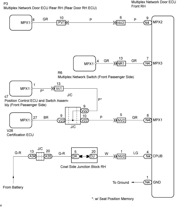
WIRING DIAGRAM
INSPECTION PROCEDURE
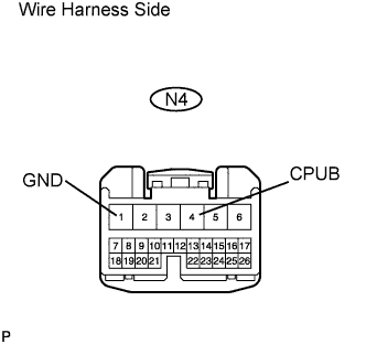
| 1.CHECK WIRE HARNESS (MULTIPLEX NETWORK DOOR ECU FRONT RH (FRONT DOOR ECU RH) - BATTERY AND BODY GROUND) |
Disconnect the N4 ECU connector.
Measure the voltage and resistance of the wire harness side connector.
- Standard voltage:
Tester Connection
| Specified Condition
|
N4-4 (CPUB) - Body ground
| 10 to 14 V
|
- Standard resistance:
Tester Connection
| Specified Condition
|
N4-1 (GND) - Body ground
| Below 1 Ω
|
| | REPAIR OR REPLACE HARNESS AND CONNECTOR |
|
|
| 2.CHECK RESISTANCE OF COMMUNICATION LINE |
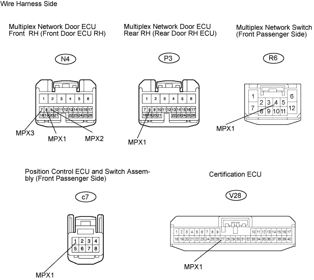
Disconnect the N4, P3, V28 and R6 ECU connectors.
Disconnect the c7 switch connector.
Measure the resistance of the wire harness side connectors.
- Standard resistance:
Tester Connection
| Specified Condition
|
N4-7 (MPX3) - R6-4 (MPX1)
| Below 1 Ω
|
N4-8 (MPX1) - c7-1 (MPX1)
| Below 1 Ω
|
N4-9 (MPX2) - P3-8 (MPX1)
| Below 1 Ω
|
N4-8 (MPX1) - V28-27 (MPX1)
| Below 1 Ω
|
- Result:
Result
| Proceed to
|
All are OK
| A
|
One or two is / are OK
| B
|
All are NG
| C
|
| | REPLACE MULTIPLEX NETWORK DOOR ECU FRONT RH AND HARNESS AND CONNECTOR |
|
|
| | REPAIR OR REPLACE HARNESS AND CONNECTOR |
|
|
| A |
|
|
|
| REPLACE MULTIPLEX NETWORK DOOR ECU FRONT RH (FRONT DOOR ECU RH) |
|