Dtc B1278 Combination Switch Ecu Communication Stop
DESCRIPTION
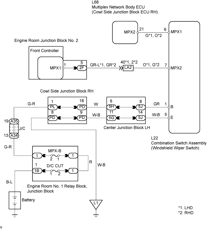
WIRING DIAGRAM
INSPECTION PROCEDURE
CHECK OPERATION
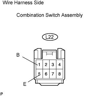
CHECK WIRE HARNESS (COMBINATION SWITCH ASSEMBLY (WINDSHIELD WIPER SWITCH) - BATTERY AND BODY GROUND)
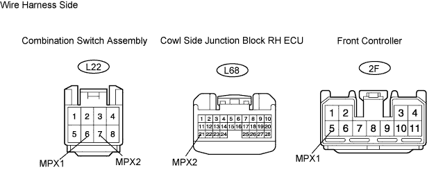
CHECK RESISTANCE OF COMMUNICATION LINE
DTC B1278 Combination Switch ECU Communication Stop |
DESCRIPTION
This DTC is detected when communication between the combination switch (windshield wiper switch) and network gateway ECU stops for more than 10 seconds.DTC No.
| DTC Detection Condition
| Trouble Area
|
B1278
| Combination switch ECU communication stops
| - Combination switch assembly (windshield wiper switch)
- Wire harness
|
WIRING DIAGRAM
INSPECTION PROCEDURE
Check that the windshield wiper switch can operate the wipers normally.
- OK:
- Windshield wiper switch can operate wipers normally.
| OK |
|
|
|
| REPLACE WINDSHIELD WIPER SWITCH ASSEMBLY |
|
| 2.CHECK WIRE HARNESS (COMBINATION SWITCH ASSEMBLY (WINDSHIELD WIPER SWITCH) - BATTERY AND BODY GROUND) |
Disconnect the L22 combination switch connector.
Measure the resistance and voltage of the wire harness side connector.
- Standard Resistance:
Tester Connection
| Specified Condition
|
L22-5 (E) - Body ground
| Below 1 Ω
|
- Standard Voltage:
Tester Connection
| Specified Condition
|
L22-1 (B) - Body ground
| 10 to 14 V
|
| | REPAIR OR REPLACE HARNESS AND CONNECTOR |
|
|
| 3.CHECK RESISTANCE OF COMMUNICATION LINE |
Disconnect the L22 switch connector.
Disconnect the L68 ECU and 2F Front Controller ECU connectors.
Measure the resistance of the wire harness side connectors.
- Standard resistance:
Tester Connection
| Specified Condition
|
L22-6 (MPX1) - L68-21 (MPX2)
| Below 1 Ω
|
L22-7 (MPX2) - 2F-5 (MPX1)
| Below 1 Ω
|
- Result:
Result
| Proceed to
|
Both are OK
| A
|
One is OK
| B
|
Both are NG
| C
|
| | REPLACE WINDSHIELD WIPER SWITCH ASSEMBLY AND HARNESS AND CONNECTOR |
|
|
| | REPAIR OR REPLACE HARNESS AND CONNECTOR |
|
|
| A |
|
|
|
| REPLACE COMBINATION SWITCH ASSEMBLY (WINDSHIELD WIPER SWITCH ASSEMBLY) |
|