DESCRIPTION
WIRING DIAGRAM
INSPECTION PROCEDURE
CHECK WIRE HARNESS (CERTIFICATION ECU - BATTERY AND BODY GROUND)
CHECK RESISTANCE OF COMMUNICATION LINE
DESCRIPTION
- HINT:
- This DTC is only output on vehicles equipped with a smart access with push-button start.
- This DTC is detected when communication between the certification ECU and gateway ECU stops for more than 10 seconds.
DTC No.
| DTC Detection Condition
| Trouble Area
|
B1207
| BEAN certification ECU communication stops
| - Certification ECU assembly
- Wire harness
|
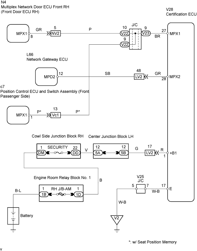
WIRING DIAGRAM
INSPECTION PROCEDURE
| 1.CHECK WIRE HARNESS (CERTIFICATION ECU - BATTERY AND BODY GROUND) |
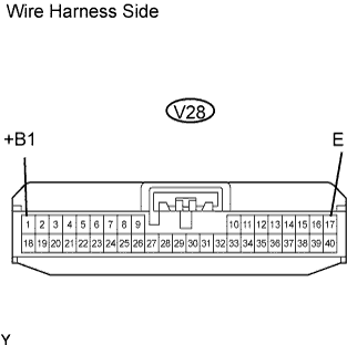
Disconnect the V28 ECU connector.
Measure the resistance and voltage of the wire harness side connector.
- Standard voltage:
Tester Connection
| Specified Condition
|
V28-1 (+B1) - Body ground
| 10 to 14 V
|
- Standard resistance:
Tester Connection
| Specified Condition
|
V28-17 (E) - Body ground
| Below 1 Ω
|
| | REPAIR OR REPLACE HARNESS AND CONNECTOR |
|
|
| 2.CHECK RESISTANCE OF COMMUNICATION LINE |
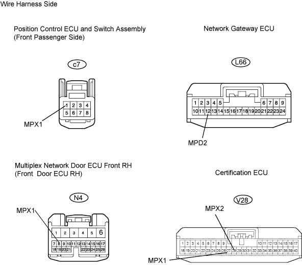
Disconnect the c7, L66, N4 and V28 ECU connectors.
Measure the resistance of the wire harness side connectors.
- Standard resistance:
Tester Connection
| Specified Condition
|
V28-27 (MPX1) - N4-8 (MPX1)
| Below 1 Ω
|
V28-27 (MPX1) - c7-1 (MPX1)
| Below 1 Ω
|
V28-28 (MPX2) - L66-12 (MPD2)
| Below 1 Ω
|
- Result:
Result
| Proceed to
|
Both are OK
| A
|
One or two is / are OK
| B
|
Both are NG
| C
|
| | REPLACE CERTIFICATION ECU AND HARNESS AND CONNECTOR |
|
|
| | REPAIR OR REPLACE HARNESS AND CONNECTOR |
|
|
| A |
|
|
|
| REPLACE CERTIFICATION ECU |
|