Multiplex Communication System -- Terminals Of Ecu |
| CHECK NETWORK GATEWAY ECU |
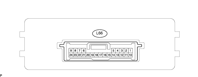
Disconnect the L66 ECU connector.
Measure the voltage and resistance of the wire harness side connector.
If the result is not as specified, there may be a malfunction on the wire harness side.Symbols (Terminal No.) Wiring Color Terminal Description Condition Specified Condition BATT (L66-10) - GND (L66-24) G - W-B +B (BATT) power supply Always 10 to 14 V IG (L66-1) - Body ground B - Body ground Ignition power supply Engine switch on (IG) 10 to 14 V ACC (L66-2) - Body ground V - Body ground ACC power supply Engine switch on (ACC) 10 to 14 V SIL (L66-7) - Body ground O - Body ground Bus ''+'' line During transmission Pulse generation MPI1 (L66-4) - Body ground LG - Body ground MPX line Always 10 kΩ or higher MPI2 (L66-13) - Body ground GR - Body ground MPX line Always 10 kΩ or higher MPL1 (L66-5) - Body ground W - Body ground MPX line Always 10 kΩ or higher MPL2 (L66-14) - Body ground GR - Body ground MPX line Always 10 kΩ or higher MPD1 (L66-3) - Body ground P - Body ground MPX line Always 10 kΩ or higher MPD2 (L66-12) - Body ground SB - Body ground MPX line Always 10 kΩ or higher GND (L66-24) - Body ground W-B - Body ground Ground Always Below 1 Ω
| CHECK ENGINE ROOM NO. 2 RELAY BLOCK (FRONT CONTROLLER) |
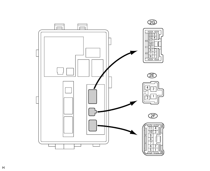
Disconnect the 2E and 2F junction block connectors.
Measure the voltage and resistance of the wire harness side connectors.
Symbol (Terminal No.) Wiring Color Terminal Description Condition Specified Condition FMB3 (2E-4) - E (2F-1) G-R - W-B +B (FMB3) power supply Always 10 to 14 V MPX1 (2F-5) - E (2F-1) GR-L*1, GR*2 - W-B MPX line Always 10 kΩ or higher MPX2 (2F-6) - E (2F-1) GR-L - W-B MPX line Always 10 kΩ or higher E (2F-1) - Body ground W-B - Body ground Ground Always Below 1 Ω - HINT:
- *1: LHD
- *2: RHD
| CHECK COWL SIDE JUNCTION BLOCK LH (COWL SIDE JUNCTION BLOCK ECU LH) |
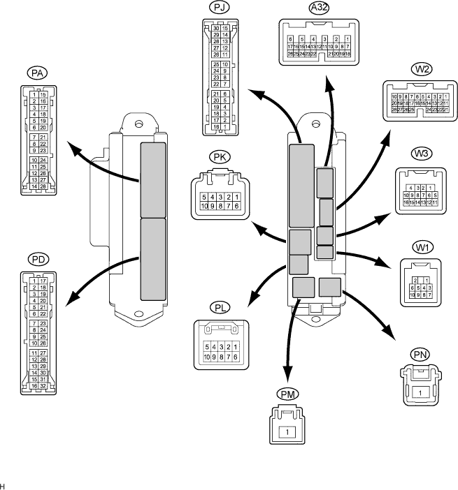
Disconnect the PA, PD and PL junction block connectors.
Disconnect the A32 and W3 ECU connectors.
Measure the resistance and voltage of the wire harness side connectors.
If the result is not as specified, there may be a malfunction on the wire harness side.Symbols (Terminal No.) Wiring Color Terminal Description Condition Specified Condition MPX-B (PL-1) - GND (PA-14) G-R - W-B +B (MPX-B) power supply Always 10 to 14 V MPX1 (W3-15) - Body ground GR - Body ground MPX line Always 10 kΩ or higher MPX4 (A32-6) - Body ground G-R - Body ground MPX line Always 10 kΩ or higher GND (PA-14) - Body ground W-B - Body ground Ground Always Below 1 Ω SGND (PD-8) - Body ground W-B - Body ground Ground Always Below 1 Ω
| CHECK COWL SIDE JUNCTION BLOCK RH (MULTIPLEX NETWORK BODY ECU) |
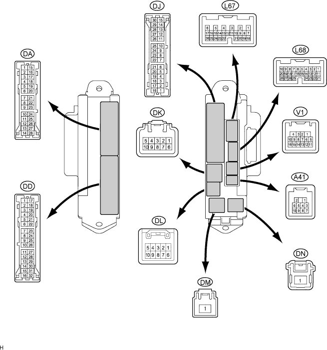
Disconnect the DA, DD and DK junction block connectors.
Disconnect the L68 ECU connector.
Measure the resistance and voltage of the wire harness side connectors.
Symbols (Terminal No.) Wiring Color Terminal Description Condition Specified Condition BECU (DK-5) - GND2 (DD-7) G-R - W-B +B (MPX-B) power supply Always 10 to 14 V MPX1 (DA-26) - GND2 (DD-7) GR - W-B MPX line Always 10 kΩ or higher MPX2 (L68-21) - GND2 (DD-7) G*1, O*2 - W-B MPX line Always 10 kΩ or higher GSW (DA-7) - GND2 (DD-7) B - W-B MPX line Always 10 kΩ or higher GND2 (DD-7) - Body ground W-B - Body ground Ground Always Below 1 Ω - HINT:
- *1: LHD
- *2: RHD
| CHECK NO. 1 JUNCTION BLOCK ASSEMBLY (MULTIPLEX NETWORK REAR ECU) |
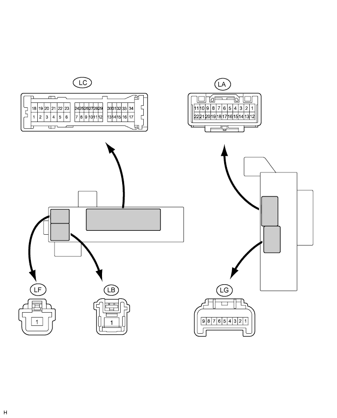
Disconnect the LB, LC and LF junction block connectors.
Measure the resistance and voltage of the wire harness side connectors.
If the result is not as specified, there may be a malfunction on the wire harness side.Symbols (Terminal No.) Wiring Color Terminal Description Condition Specified Condition RFRL (LB-1) - Body ground B - Body ground +B (MPX-B) power supply Always 10 to 14 V MPX1 (LC-21) - Body ground BR - Body ground MPX line Always 10 kΩ or higher MPX2 (LC-31) - Body ground) GR - Body ground MPX line Always 10 kΩ or higher P-GND (LF-1) - Body ground W-B - Body ground Ground Always Below 1 Ω SG (LC-3) - Body ground W-B - Body ground Ground Always Below 1 Ω
| CHECK MULTIPLEX NETWORK DOOR ECU FRONT LH (FRONT DOOR ECU LH) |
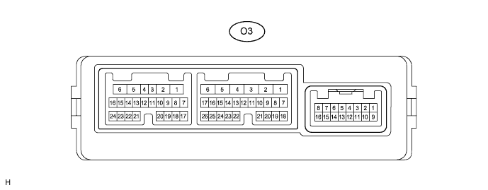
Disconnect the O3 ECU connector.
Measure the voltage and resistance of the wire harness side connector.
If the result is not as specified, there may be a malfunction on the wire harness side.Symbols (Terminal No.) Wiring Color Terminal Description Condition Specified Condition CPUB (O3-4) - Body ground LG - Body ground +B (CPUB) power supply Always 10 to 14 V BDR (O3-6) - Body ground L - Body ground +B (BDR) power supply Always 10 to 14 V MPX1 (O3-8) - Body ground P - Body ground MPX line Always 10 kΩ or higher MPX2 (O3-9) - Body ground L - Body ground MPX line Always 10 kΩ or higher GND (O3-1) - Body ground W-B - Body ground Ground Always Below 1 Ω
| CHECK MULTIPLEX NETWORK DOOR ECU FRONT RH (FRONT DOOR ECU RH) |

Disconnect the N4 ECU connector.
Measure the voltage and resistance of the wire harness side connector.
If the result is not as specified, there may be a malfunction on the wire harness side.Symbols (Terminal No.) Wiring Color Terminal Description Condition Specified Condition CPUB (N4-4) - Body ground LG - Body ground +B (CPUB) power supply Always 10 to 14 V BDR (N4-6) - Body ground L - Body ground +B (BDR) power supply Always 10 to 14 V MPX1 (N4-8) - Body ground GR - Body ground MPX line Always 10 kΩ or higher MPX2 (N4-9) - Body ground P - Body ground MPX line Always 10 kΩ or higher GND (N4-1) - Body ground W-B - Body ground Ground Always Below 1 Ω
| CHECK MULTIPLEX NETWORK DOOR ECU REAR LH (REAR DOOR LH) |
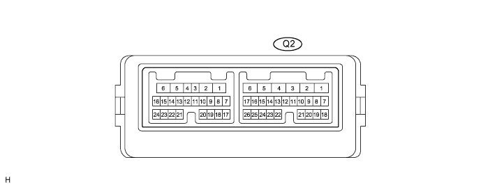
Disconnect the Q2 ECU connector.
Measure the voltage and resistance of the wire harness side connector.
If the result is not as specified, there may be a malfunction on the wire harness side.Symbols (Terminal No.) Wiring Color Terminal Description Condition Specified Condition CPUB (Q2-4) - Body ground BR - Body ground +B (CPUB) power supply Always 10 to 14 V BDR (Q2-6) - Body ground L - Body ground +B (BDR) power supply Always 10 to 14 V MPX1 (Q2-8) - Body ground GR - Body ground MPX line Always 10 kΩ or higher MPX2 (Q2-9) - Body ground P - Body ground MPX line Always 10 kΩ or higher GND (Q2-1) - Body ground W-B - Body ground Ground Always Below 1 Ω
| CHECK MULTIPLEX NETWORK DOOR ECU REAR RH (REAR DOOR RH) |
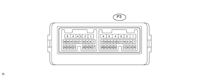
Disconnect the P3 ECU connector.
Measure the voltage the resistance of the wire harness side connector.
If the result is not as specified, there may be a malfunction on the wire harness side.Symbols (Terminal No.) Wiring Color Terminal Description Condition Specified Condition CPUB (P3-4) - Body ground G - Body ground +B (CPUB) power supply Always 10 to 14 V BDR (P3-6) - Body ground L - Body ground +B (BDR) power supply Always 10 to 14 V MPX1 (P3-8) - Body ground GR - Body ground MPX line Always 10 kΩ or higher MPX2 (P3-9) - Body ground P - Body ground MPX line Always 10 kΩ or higher GND (P3-1) - Body ground W-B - Body ground Ground Always Below 1 Ω
| CHECK POSITION CONTROL ECU AND SWITCH ASSEMBLY (DRIVER SIDE) |
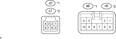
Disconnect the d7*1, c7*2 and d8*1, c6*2 ECU connectors.
Measure the voltage and the resistance of the wire harness side connectors.
Symbols (Terminal No.) Wiring Color Terminal Description Condition Specified Condition +B (d7-5)*1 - GND (d7-1)*1 L - W-B +B (+B) power supply Always 10 to 14 V +B (c7-5)*2 - GND (c7-1)*2 L - W-B +B (+B) power supply Always 10 to 14 V SYSB (d7-8)*1 - Body ground G - Body ground +B (SYSB) power supply Always 10 to 14 V SYSB (c7-8)*2 - Body ground R - Body ground +B (SYSB) power supply Always 10 to 14 V MPX1 (d7-1)*1 - Body ground G-R - Body ground MPX line Always 10 kΩ or higher MPX1 (c7-1)*2 - Body ground P - Body ground MPX line Always 10 kΩ or higher GND (d8-1)*1 - Body ground W-B - Body ground Ground Always Below 1 Ω GND (c6-1)*2 - Body ground W-B - Body ground Ground Always Below 1 Ω - HINT:
- *1: LHD
- *2: RHD
| CHECK NO. 2 AIR CONDITIONING AMPLIFIER ASSEMBLY (A/C ECU) |
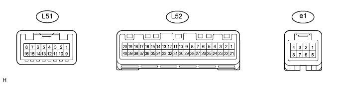
Disconnect the L52 amplifier connector.
Measure the voltage and resistance of the wire harness side connector.
If the result is not as specified, there may be a malfunction on the wire harness side.Symbols (Terminal No.) Wiring Color Terminal Description Condition Specified Condition B (L52-1) - GND (L52-20) L - W-B +B power supply Always 10 to 14 V IG+ (L52-21) - Body ground W - Body ground Engine switch signal (IG) Engine switch on (IG) 10 to 14 V MPX+ (L52-30) - Body ground SB - Body ground MPX line Always 10 kΩ or higher MPX- (L52-31) - Body ground Y - Body ground MPX line Always 10 kΩ or higher GND (L52-20) - Body ground W-B - Body ground Ground Always Below 1 Ω
| CHECK AIRBAG SENSOR ASSEMBLY CENTER |
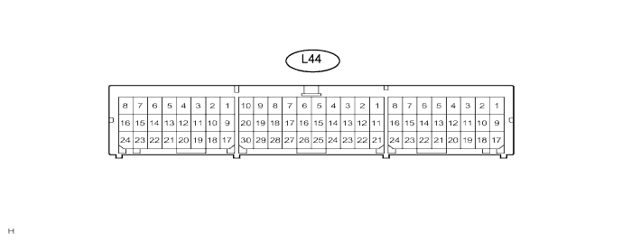
Disconnect the L44 sensor connector.
Measure the voltage and resistance of the wire harness side connector.
If the result is not as specified, there may be a malfunction on the wire harness side.Symbols (Terminal No.) Wiring Color Terminal Description Condition Specified Condition IG2 (L44-21) - E1(L44-25) B - W-B Engine switch signal (IG) Engine switch on (IG) 10 to 14 V MPX1 (L44-13) - Body ground R - Body ground MPX line Always 10 kΩ or higher MPX2 (L44-22) - Body ground R - Body ground MPX line Always 10 kΩ or higher E1 (L44-25) - Body ground W-B - Body ground Ground Always Below 1 Ω E2 (L44-26) - Body ground W-B - Body ground Ground Always Below 1 Ω
| CHECK COMBINATION METER ASSEMBLY (METER ECU) |
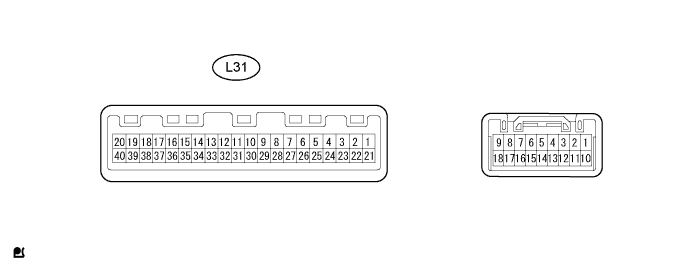
Disconnect the L31 meter connector.
Measure the voltage and resistance of the wire harness side connector.
If the result is not as specified, there may be a malfunction on the wire harness side.Symbols (Terminal No.) Wiring Color Terminal Description Condition Specified Condition B (L31-21) - Body ground B - Body ground +B (B) power supply Always 10 to 14 V B (L31-22) - Body ground L - Body ground +B (B) power supply Always 10 to 14 V MPX+ (L31-25) - Body ground GR - Body ground MPX line Always 10 kΩ or higher MPX- (L31-5) - Body ground SB - Body ground MPX line Always 10 kΩ or higher E2 (L31-40) - Body ground W-B - Body ground Ground Always Below 1 Ω
| CHECK SLIDING ROOF DRIVE GEAR SUB-ASSEMBLY (SLIDING ROOF CONTROL ECU) |

Disconnect the Y11 driver gear connector.
Measure the voltage and the resistance of the wire harness side connector.
If the result is not as specified, there may be a malfunction on the wire harness side.Symbols (Terminal No.) Wiring Color Terminal Description Condition Specified Condition B (Y11-5) - E (Y11-7) L - W-B +B (B) power supply Always 10 to 14 V MPX1 (Y11-10) - Body ground GR - Body ground MPX line Always 10 kΩ or higher E (Y11-7) - Body ground W-B - Body ground Ground Always Below 1 Ω
| CHECK MULTIPLEX TILT AND TELESCOPIC ECU |
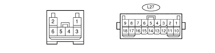
Disconnect the L27 ECU connector.
Measure the voltage and resistance of the wire harness side connector.
If the result is not as specified, there may be a malfunction on the wire harness side.Symbols (Terminal No.) Wiring Color Terminal Description Condition Specified Condition ECUB (L27-9) - GND (L27-11) R - W-B +B (ECUB) power supply Always 11 to 14 V +B (L27-2) - GND (L27-11) L - W-B +B (+B) power supply Always 11 to 14 V MPX1 (L27-5) - Body ground GR - Body ground MPX line Always 10 kΩ or higher E (L27-11) - Body ground W-B - Body ground Ground Always Below 1 Ω
| CHECK COMBINATION SWITCH ASSEMBLY (WINDSHIELD WIPER SWITCH) |

Disconnect the L22 switch connector.
Measure the voltage and resistance of the wire harness side connector.
Symbols (Terminal No.) Wiring Color Terminal Description Condition Specified Condition B (L22-1) - E (L22-5) GR - W-B +B (B) power supply Always 10 to 14 V MPX1 (L22-6) - Body ground G*1, O*2 - Body ground MPX line Always 10 kΩ or higher MPX2 (L22-7) - Body ground O*1, G*2 - Body ground MPX line Always 10 kΩ or higher E (L22-5) - Body ground W-B - Body ground Ground Always Below 1 Ω - HINT:
- *1: LHD
- *2: RHD
| CHECK MULTIPLEX NETWORK MASTER SWITCH ASSEMBLY |
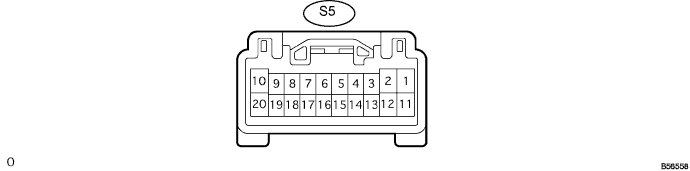
Disconnect the S5 switch connector.
Measure the voltage and resistance of the wire harness side connector.
If the result is not as specified, there may be a malfunction on the wire harness side.Symbols (Terminal No.) Wiring Color Terminal Description Condition Specified Condition CPUB (S5-9) - E (S5-2) G - W-B +B (CPUB) power supply Always 10 to 14 V E (S5-2) - Body ground W-B - Body ground Ground Always Below 1 Ω MPX1 (S5-7) - E (S5-2) GR - W-B MPX line Always Below 1 Ω MPX2 (S5-8) - E (S5-2) P - W-B MPX line Always Below 1 Ω
| CHECK POWER SOURCE CONTROL ECU |

Disconnect the L73 ECU connector.
Measure the voltage and resistance of the wire harness side connector.
If the result is not as specified, there may be a malfunction on the wire harness side.Symbols (Terminal No.) Wiring Color Terminal Description Condition Specified Condition AM1 (L73-33) - GND2 (L73-6) O - W-B +B power supply Always 10 to 14 V AM2 (L73-12) - GND2 (L73-6) BR - W-B +B power supply Always 10 to 14 V MPX1 (L73-7) - Body ground LG - Body ground MPX line Always 10 kΩ or higher GND2 (L73-6) - Body ground W-B - Body ground Ground Always Below 1 Ω
| CHECK CERTIFICATION ECU |
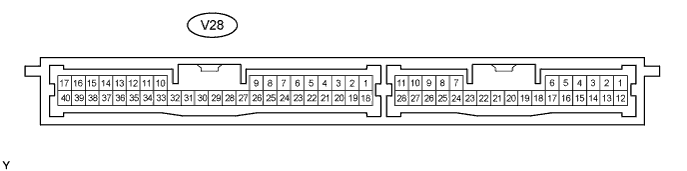
Disconnect the V28 ECU connector.
Measure the resistance and voltage of the wire harness side connector.
If the result is not as specified, there may be a malfunction on the wire harness side.Symbols (Terminal No.) Wiring Color Terminal Description Condition Specified Condition +B1 (V28-1) - E (V28-17) R - W-B B power supply Always 10 to 14 V MPX1 (V28-27) - E (V28-17) BR - W-B MPX line Always 10 kΩ or higher MPX2 (V28-28) - E (V28-17) GR - W-B MPX line Always 10 kΩ or higher E (V28-17) - Body ground W-B - Body ground Ground Always Below 1 Ω
| CHECK TIRE PRESSURE WARNING ECU |
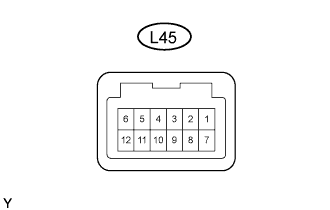
Disconnect the L45 ECU connector.
Measure the resistance and voltage of the wire harness side connector.
If the result is not as specified, there may be a malfunction on the wire harness side.Symbols (Terminal No.) Wiring Color Terminal Description Condition Specified Condition IG (L45-1) - GND (L45-7) G - W-B Power supply Always 10 to 14 V MPX1 (L45-6) - GND (L45-7) LG - W-B MPX line Always 10 kΩ or higher MPX2 (L45-12) - GND (L45-7) GR - W-B MPX line Always 10 kΩ or higher GND (L45-7 ) - Body ground W-B - Body ground Ground Always Below 1 Ω