Navigation Ecu -- Installation |
- HINT:
- A bolt without a torque specification is shown in the standard bolt chart (Click here).
| 1. INSTALL NO. 2 DISC PLAYER BRACKET |
Install the bracket's aligning protrusions labeled A to the ECU.
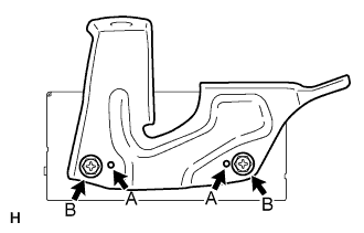 |
Install the 2 screws labeled B.
| 2. INSTALL NO. 1 DISC PLAYER BRACKET |
Install the bracket's aligning protrusions labeled A to the ECU.
 |
Install the 2 screws labeled B.
| 3. INSTALL NAVIGATION ECU WITH DISC PLAYER BRACKET |
Install the navigation ECU with bracket with the 3 bolts.
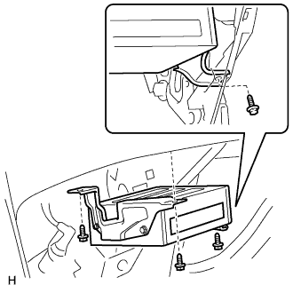 |
Connect the connectors.
| 4. INSTALL GLOVE COMPARTMENT DOOR SUB-ASSEMBLY |
 |
Attach the 2 clips and claw to install the glove compartment door.
Connect the connector and clamp.
Install the 4 screws.
| 5. INSTALL FRONT PASSENGER SIDE KNEE AIRBAG ASSEMBLY |
Connect the connector.
- NOTICE:
- When handling the airbag connector, take care not to damage the airbag wire harness.
 |
Install the front passenger side knee airbag assembly with the 3 bolts.
- Torque:
- 10 N*m{102 kgf*cm, 7 ft.*lbf}
| 6. INSTALL NO. 2 INSTRUMENT PANEL UNDER COVER SUB-ASSEMBLY |
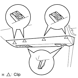 |
Connect the connector and clamp.
Attach the 4 clips to install the under cover.
| 7. INSTALL INSTRUMENT SIDE PANEL RH |
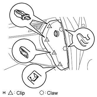 |
Attach the 2 claws and 4 clips to install the side panel.
| 8. INSTALL FRONT DOOR OPENING TRIM COVER RH |
- HINT:
- Use the same procedures described for the LH side.
| 9. INSTALL FRONT DOOR SCUFF PLATE RH |
- HINT:
- Use the same procedures described for the LH side.
| 10. INSTALL INSTRUMENT PANEL FINISH PANEL END RH |
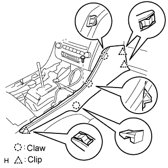 |
Attach the 3 clips and 3 claws to install the finish panel end.
Install the screw.
| 11. INSTALL CONSOLE UPPER PANEL ASSEMBLY |
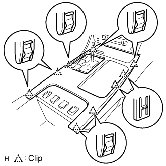 |
Connect the connector.
Attach the 9 clips to install the ash receptacle.
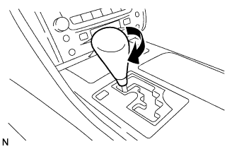
Install the shift lever knob and twist it in the direction indicated by the arrow.
 |
| 12. INSTALL FRONT CONSOLE UPPER PANEL GARNISH |
Attach the claws to install the garnish.
| 13. CONNECT CABLE TO NEGATIVE BATTERY TERMINAL |
| 14. PERFORM INITIALIZATION |
Perform initialization (Click here).
- NOTICE:
- Certain systems need to be initialized after disconnecting and reconnecting the cable from the negative (-) battery terminal.
| 15. CHECK SRS WARNING LIGHT |
Check the SRS warning light (Click here).