Navigation System Navigation Ecu Power Source Circuit
DESCRIPTION
WIRING DIAGRAM
INSPECTION PROCEDURE
CHECK MULTI-DISPLAY POWER SOURCE CIRCUIT
CHECK MULTI-DISPLAY
NAVIGATION SYSTEM - Navigation ECU Power Source Circuit |
DESCRIPTION
This circuit provides the power to the navigation ECU.
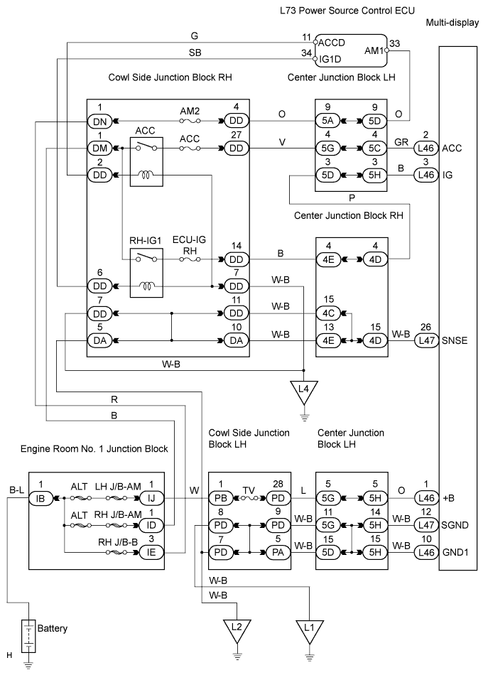
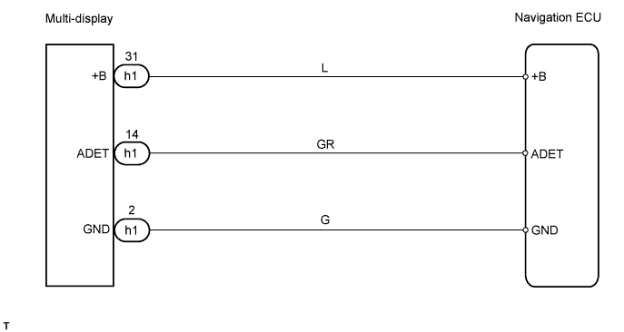
WIRING DIAGRAM
The wiring diagram is shown below.
INSPECTION PROCEDURE
| 1.CHECK MULTI-DISPLAY POWER SOURCE CIRCUIT |
Refer to the "multi-display power source circuit" (Click here).If the power source circuit is operating normally, proceed to the next step.
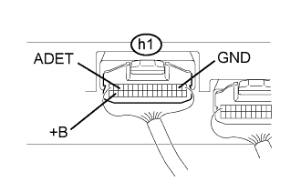
Measure the voltage of the connector.
- Standard voltage:
Tester Connection
| Condition
| Specified Condition
|
h1-31 (+B) - Body ground
| Always
| 10 to 14 V
|
h1-14 (ADET) - Body ground
| Engine switch on (ACC)
| 10 to 14 V
|
Measure the resistance of the connector.
- Standard resistance:
Tester Connection
| Condition
| Specified Condition
|
h1-2 (GND) - Body ground
| Always
| Below 1 Ω
|