Navigation System Vehicle Speed Signal Circuit Between Multi-Display And Combination Meter
DESCRIPTION
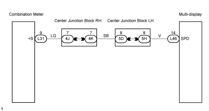
WIRING DIAGRAM
INSPECTION PROCEDURE
CHECK WIRE HARNESS (COMBINATION METER - MULTI-DISPLAY)
CHECK COMBINATION METER
NAVIGATION SYSTEM - Vehicle Speed Signal Circuit between Multi-display and Combination Meter |
DESCRIPTION
The multi-display performs the switch operation control while the vehicle is running by receiving the vehicle speed signal from the combination meter.
WIRING DIAGRAM
INSPECTION PROCEDURE
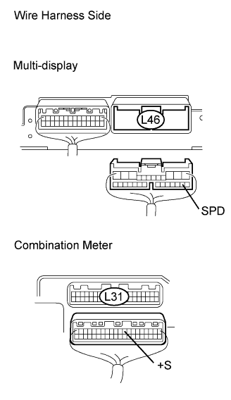
| 1.CHECK WIRE HARNESS (COMBINATION METER - MULTI-DISPLAY) |
Disconnect the L46 multi-display connector.
Disconnect the L31 meter connector.
Measure the resistance of the wire harness side connectors.
- Standard resistance:
Tester Connection
| Condition
| Specified Condition
|
L46-14 (SPD) - L31-9 (+S)
| Always
| Below 1 Ω
|
L46-14 (SPD) - Body ground
| Always
| 10 kΩ or higher
|
| | REPAIR OR REPLACE HARNESS AND CONNECTOR |
|
|
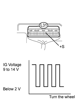
| 2.CHECK COMBINATION METER |
Connect the L31 meter connector.
Measure the voltage.
Move the shift lever to the neutral position.
Jack up either one of the rear wheels.
Turn the engine switch on (IG).
Measure the voltage between terminal +S and body ground of the combination meter when the rear wheels are turned slowly.
- Standard voltage:
Tester Connection
| Condition
| Specified Condition
|
L31-9 (+S) - Body ground
| Engine switch on (IG), rear wheels turned slowly
| Voltage pulses as shown
|
| | GO TO COMBINATION METER SYSTEM |
|
|