Navigation System Parking Brake Switch Circuit
DESCRIPTION
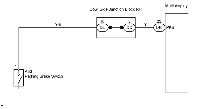
WIRING DIAGRAM
INSPECTION PROCEDURE
CHECK BRAKE WARNING LIGHT
INSPECT PARKING BRAKE SWITCH
CHECK WIRE HARNESS (PARKING BRAKE SWITCH - MULTI-DISPLAY)
NAVIGATION SYSTEM - Parking Brake Switch Circuit |
DESCRIPTION
This is the circuit from the parking brake switch to the multi-display.
WIRING DIAGRAM
INSPECTION PROCEDURE
| 1.CHECK BRAKE WARNING LIGHT |
Check that the brake warning light illuminates when the parking brake pedal is depressed, and goes off when the parking brake pedal is released.
- OK:
- The brake warning light operates as specified above.
| 2.INSPECT PARKING BRAKE SWITCH |
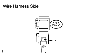
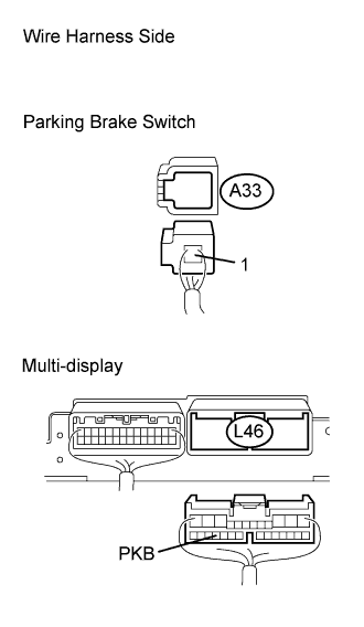
Disconnect the A33 switch connector.
Measure the resistance of the wire harness side connector.
- Standard resistance:
Tester Connection
| Switch Condition
| Specified Condition
|
Switch connector - Switch body
| Pushed
| Below 1 Ω
|
Switch connector - Switch body
| Not pushed
| 10 kΩ or higher
|
| | REPLACE PARKING BRAKE SWITCH |
|
|
| 3.CHECK WIRE HARNESS (PARKING BRAKE SWITCH - MULTI-DISPLAY) |
Disconnect the L46 multi-display connector.
Disconnect the A33 switch connector.
Measure the resistance of the wire harness side connectors.
- Standard resistance:
Tester Connection
| Condition
| Specified Condition
|
L46-23 (PKB) - A33-1
| Always
| Below 1 Ω
|
L46-23 (PKB) - Body ground
| Always
| 10 kΩ or higher
|
| | REPAIR OR REPLACE HARNESS AND CONNECTOR |
|
|
| OK |
|
|
|
| PROCEED TO NEXT CIRCUIT INSPECTION SHOWN IN PROBLEM SYMPTOMS TABLE |
|