Land Cruiser URJ200 URJ202 GRJ200 VDJ200 - 3UR-FE INTAKE / EXHAUST
EXHAUST MANIFOLD - REMOVAL
| 1. REMOVE FRONT FENDER SPLASH SHIELD SUB-ASSEMBLY LH |
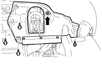
Remove the 3 bolts and screw.
Turn the clip indicated by the arrow in the illustration to remove the front fender splash shield sub-assembly LH.
| 2. REMOVE FRONT FENDER SPLASH SHIELD SUB-ASSEMBLY RH |
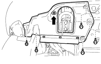
Remove the 3 bolts and 2 screws.
Turn the clip indicated by the arrow in the illustration to remove the front fender splash shield sub-assembly RH.
| 3. REMOVE NO. 1 ENGINE UNDER COVER SUB-ASSEMBLY |

Remove the 10 bolts and No. 1 engine under cover.
| 4. REMOVE NO. 2 ENGINE UNDER COVER |
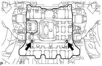
Remove the 2 bolts and No. 2 engine under cover.
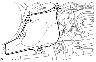
| 5. REMOVE FRONT FENDER APRON SEAL FRONT RH |

Using a clip remover, remove the 3 clips and fender apron seal.
| 6. REMOVE FRONT FENDER APRON SEAL REAR RH |
Using a clip remover, remove the 4 clips and fender apron seal.
| 7. REMOVE FRONT FENDER APRON SEAL LH |

Using a clip remover, remove the 3 clips and fender apron seal.
| 8. REMOVE FRONT FENDER APRON SEAL REAR LH |

Using a clip remover, remove the 4 clips and fender apron seal.
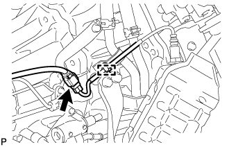
| 9. REMOVE ENGINE OIL LEVEL DIPSTICK GUIDE |

Disconnect the wire harness clamp.
Remove the dipstick.
Remove the bolt and dipstick guide.
Remove the O-ring from the dipstick guide.
| 10. REMOVE TAILPIPE ASSEMBLY |
Remove the bolt, clamp and gasket.
Remove the tailpipe from the 2 exhaust pipe supports.
Remove the bolt and clamp, and then disconnect the tailpipe from the center exhaust pipe.
| 11. REMOVE CENTER EXHAUST PIPE ASSEMBLY |
Remove the 4 bolts.
Remove the center exhaust pipe from the 3 exhaust pipe supports.
Remove the 2 gaskets from the front exhaust pipe and front No. 2 exhaust pipe.
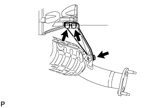
| 12. REMOVE FRONT NO. 2 EXHAUST PIPE ASSEMBLY |
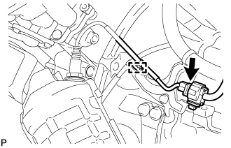
Disconnect the heated oxygen sensor connector.
Remove the bolt and disconnect the wire harness clamp bracket of the oxygen sensor from the transmission.
Remove the 2 nuts, front No. 2 exhaust pipe and gasket from the exhaust manifold LH.
| 13. REMOVE FRONT EXHAUST PIPE ASSEMBLY |
Disconnect the heated oxygen sensor connector.
Remove the bolt and disconnect the wire harness clamp bracket of the oxygen sensor from the transmission.
Remove the 2 nuts, front exhaust pipe and gasket from the exhaust manifold RH.
| 14. REMOVE PROPELLER SHAFT HEAT INSULATOR |

Remove the 2 bolts and heat insulator.
| 15. REMOVE NO. 2 MANIFOLD STAY |
Remove the 3 bolts and No. 2 manifold stay.
| 16. REMOVE NO. 2 EXHAUST MANIFOLD HEAT INSULATOR |

Remove the 3 bolts and heat insulator.
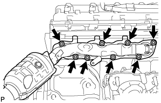
| 17. REMOVE EXHAUST MANIFOLD SUB-ASSEMBLY LH |
Disconnect the connector and detach the wire harness clamp.
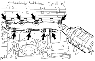
Remove the 8 nuts, exhaust manifold sub-assembly LH and gasket.
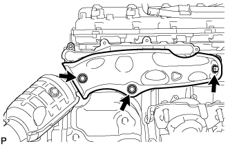
| 18. REMOVE NO. 1 MANIFOLD STAY |

Remove the 3 bolts and No. 1 manifold stay.
| 19. REMOVE NO. 1 EXHAUST MANIFOLD HEAT INSULATOR |
Remove the 3 bolts and heat insulator.
| 20. REMOVE EXHAUST MANIFOLD SUB-ASSEMBLY RH |
Disconnect the connector and detach the wire harness clamp.
Remove the 8 nuts, exhaust manifold sub-assembly RH and gasket.
| 21. REMOVE AIR FUEL RATIO SENSOR (for Bank 1 Sensor 1) |

Using SST, remove the sensor.
- SST
- 09224-00010
| 22. REMOVE AIR FUEL RATIO SENSOR (for Bank 2 Sensor 1) |
Using SST, remove the sensor.
- SST
- 09224-00010