Power Door Lock Control System Key Lock-In Prevention Function Does Not Work Properly (Manual Operation And Key-Linked Lock Are Activated)
DESCRIPTION
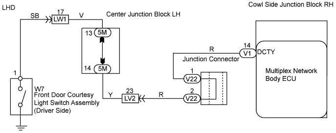
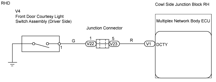
WIRING DIAGRAM
INSPECTION PROCEDURE
CHECK ENTRY AND START SYSTEM
READ VALUE OF INTELLIGENT TESTER (FRONT DOOR COURTESY LIGHT SWITCH ASSEMBLY (DRIVER SIDE))
INSPECT FRONT DOOR COURTESY LIGHT SWITCH ASSEMBLY (DRIVER SIDE)
CHECK WIRE HARNESS (MULTIPLEX NETWORK BODY ECU - DOOR COURTESY LIGHT SWITCH)
POWER DOOR LOCK CONTROL SYSTEM - Key Lock-in Prevention Function does not Work Properly (Manual Operation and Key-Linked Lock are Activated) |
DESCRIPTION
When the transmitter is in the vehicle or the door courtesy light ON signal is output to the ECU, performing the door lock operation with the lock switch on the outer handle will not lock the door.
WIRING DIAGRAM
INSPECTION PROCEDURE
| 1.CHECK ENTRY AND START SYSTEM |
Check that each function of the entry door lock operates normally by using the lock switch.
- OK:
- Entry door lock is functioning normally.
| | GO TO ENTRY AND START SYSTEM |
|
|
| 2.READ VALUE OF INTELLIGENT TESTER (FRONT DOOR COURTESY LIGHT SWITCH ASSEMBLY (DRIVER SIDE)) |
Check the Data List for proper functioning of the door courtesy light switch.
- Multiplex network body ECU:
Item
| Measurement Item/Display (Range)
| Normal Condition
| Diagnostic Note
|
D Door Courtesy SW
| Driver side door courtesy light switch signal/ON or OFF
| ON: Driver side door is unlocked
OFF: Driver side door is locked
| -
|
- OK:
- ON (driver side door is unlocked) appears on screen.
| OK |
|
|
|
| REPLACE COWL SIDE JUNCTION BLOCK RH (MULTIPLEX NETWORK BODY ECU) |
|
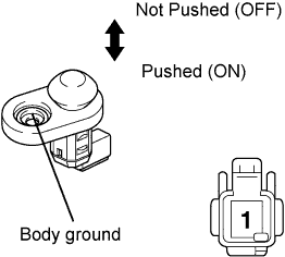
| 3.INSPECT FRONT DOOR COURTESY LIGHT SWITCH ASSEMBLY (DRIVER SIDE) |
Remove the courtesy light switch.
Measure the resistance of the switch.
- Standard resistance:
Tester Connection
| Switch Condition
| Specified Condition
|
1 - Body ground
| Not pushed (ON)
| Below 1 Ω
|
1 - Body ground
| Pushed (OFF)
| 10 kΩ or higher
|
| | REPLACE FRONT DOOR COURTESY LIGHT SWITCH ASSEMBLY (DRIVER SIDE) |
|
|
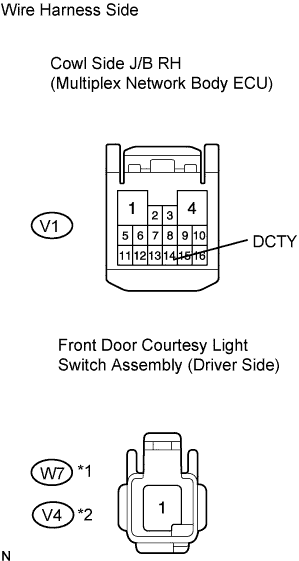
| 4.CHECK WIRE HARNESS (MULTIPLEX NETWORK BODY ECU - DOOR COURTESY LIGHT SWITCH) |
Disconnect the V1 ECU connector.
Disconnect the W7*1 or V4*2 switch connector.
Measure the resistance of the wire harness side connectors.
- Standard resistance:
LHDTester Connection
| Specified Condition
|
V1-14 (DCTY) - W7-1
| Below 1 Ω
|
- RHD:
Tester Connection
| Specified Condition
|
V1-14 (DCTY) - V4-1
| Below 1 Ω
|
- HINT:
- *1: LHD
- *2: RHD
| | REPAIR OR REPLACE HARNESS AND CONNECTOR |
|
|
| OK |
|
|
|
| REPLACE COWL SIDE JUNCTION BLOCK RH (MULTIPLEX NETWORK BODY ECU) |
|