Wiper And Washer System Terminals Of Ecu
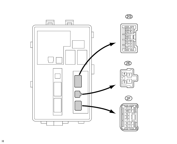
CHECK ENGINE ROOM NO. 2 JUNCTION BLOCK (FRONT CONTROLLER)
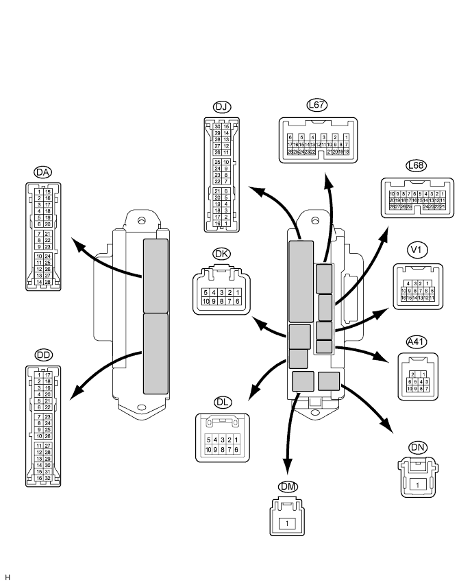
CHECK COWL SIDE JUNCTION BLOCK RH (MULTIPLEX NETWORK BODY ECU)
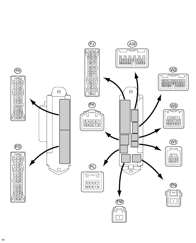
CHECK COWL SIDE JUNCTION BLOCK LH (COWL SIDE JUNCTION BLOCK ECU LH)
CHECK WINDSHIELD WIPER SWITCH (COMBINATION SWITCH ECU)
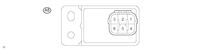
CHECK HEADLIGHT CLEANER CONTROL RELAY
Wiper And Washer System -- Terminals Of Ecu |
| CHECK ENGINE ROOM NO. 2 JUNCTION BLOCK (FRONT CONTROLLER) |
Symbols (Terminal No.)
| Wiring Color
| Terminal Description
| Condition
| Specified Condition
|
FMIG (2E-3) - E (2F-1)
| B-Y - W-B
| IG signal circuit (to IG relay)
| Engine switch off
| Below 1 V
|
Engine switch on (IG)
| 10 to 14 V
|
FMB3 (2E-4) - E (2F-1)
| G-R - W-B
| Power source circuit (from battery)
| Always
| 10 to 14 V
|
E (2F-1) - Body ground
| W-B - Body ground
| Ground circuit
| Always
| Below 1 V
|
W+ (2F-4) - E (2F-1)
| L - W-B
| Windshield washer motor circuit
| Windshield washer motor OFF
| Below 1 V
|
Windshield washer motor ON
| 10 to 14 V
|
MPX1 (2F-5) - E (2F-1)
| GR*1 - W-B
| Multiplex communication signal circuit
| Engine switch on (IG)
| Signal waveform
|
GR-L*2 - W-B
|
MPX2 (2F-6) - E (2F-1)
| GR-L - W-B
| Multiplex communication signal circuit
| Engine switch on (IG)
| Signal waveform
|
FRWA (2F-8) - E (2F-1)
| L-O - W-B
| Headlight cleaner operation signal
| Windshield washer motor OFF
| 4.5 to 5.5 V
|
Windshield washer motor ON
| Below 1 V
|
- HINT:
- *1: LHD
- *2: RHD
| CHECK COWL SIDE JUNCTION BLOCK RH (MULTIPLEX NETWORK BODY ECU) |
Symbols (Terminal No.)
| Wiring Color
| Terminal Description
| Condition
| Specified Condition
|
MPX1 (DA-20) - GND2 (DD-7)
| GR - W-B
| Multiplex communication signal circuit
| Engine switch on (IG)
| Signal waveform
|
MPX1 (DA-20) - GND2 (DD-7)
| GR - W-B
| Multiplex communication signal circuit
| Engine switch on (IG)
| Signal waveform
|
GND2 (DD-7) - Body ground
| W-B - Body ground
| Ground circuit
| Always
| Below 1 V
|
MPX1 (DA-26) - GND2 (DD-7)
| G-R - W-B
| Multiplex communication signal circuit
| Engine switch on (IG)
| Signal waveform
|
BECU (DK-5) - GND2 (DD-7)
| GR - W-B
| ECU power supply (from battery)
| Always
| 10 to 14 V
|
PKB (DL-10) - GND2 (DD-7)
| Y-B - W-B
| Parking brake switch circuit
| Parking brake pedal is depressed
| Below 1 V
|
Parking brake pedal is released
| 10 to 14 V
|
HDLO (A41-4) - GND2 (DD-7)
| R - W-B
| Headlight signal (to headlight cleaner relay)
| Headlight switch is OFF
| 10 to 14 V
|
Headlight switch is LOW
| Below 1 V
|
MPX2 (L68-21) - GND2 (DD-7)
| O*1 - W-B
| Multiplex communication signal circuit
| Engine switch on (IG)
| Signal waveform
|
G*2 - W-B
|
- HINT:
- *1: LHD
- *2: RHD
| CHECK COWL SIDE JUNCTION BLOCK LH (COWL SIDE JUNCTION BLOCK ECU LH) |
Symbols (Terminal No.)
| Wiring Color
| Terminal Description
| Condition
| Specified Condition
|
GND (PA-14) - Body ground
| W-B - Body ground
| Ground circuit
| Always
| Below 1 V
|
SGND (PD-8) - GND (PA-14)
| W-B - W-B
| Signal ground circuit
| Always
| Below 1 V
|
SGND (PD-9) - GND (PA-14)
| W-B - W-B
| Signal ground circuit
| Always
| Below 1 V
|
WIG (PK-9) - GND (PA-14)
| L - W-B
| Front wiper motor power source circuit
| Engine switch off
| Below 1 V
|
Engine switch on (IG)
| 10 to 14 V
|
MPXB (PL-1) - GND (PA-14)
| G-R - W-B
| ECU power supply (from battery)
| Always
| 10 to 14 V
|
B (PM-1) - GND (PA-14)
| W - W-B
| Power source circuit (from battery)
| Always
| 10 to 14 V
|
S/S (A32-1) - GND (PA-14)
| Y - W-B
| Front wiper motor power supply circuit (LOW signal)
| Front wiper switch OFF
| Below 1 V
|
Front wiper switch LOW
| 10 to 14 V
|
+2 (A32-2) - GND (PA-14)
| L-R - W-B
| Front wiper motor power supply circuit (HI signal)
| Front wiper switch OFF
| Below 1 V
|
Front wiper switch HI
| 10 to 14 V
|
S/M (A32-17) - GND (PA-14)
| G - W-B
| Front wiper motor operation signal
| Front wiper is operated
| 10 to 14 V
|
Front wiper is stopped
| Below 1 V
|
MPX2 (A32-17) - GND (PA-14)
| GR-L - W-B
| Multiplex communication signal circuit
| Engine switch on (IG)
| Signal waveform
|
2S (W2-11) - GND (PA-14)
| W - W-B
| Front wiper switch HI signal (to combination switch)
| Front wiper switch OFF
| 10 to 14 V
|
Front wiper switch HI
| Below 1 V
|
MPX1 (W3-15) - GND (PA-14)
| GR - W-B
| Multiplex communication signal circuit
| Engine switch on (IG)
| Signal waveform
|
| CHECK WINDSHIELD WIPER SWITCH (COMBINATION SWITCH ECU) |
Symbols (Terminal No.)
| Wiring Color
| Terminal Description
| Condition
| Specified Condition
|
B (L22-1) - E (L22-5)
| GR - W-B
| Power source circuit (from battery)
| Always
| 10 to 14 V
|
IG (L22-2) - E (L22-5)
| LG - W-B
| IG signal circuit (to IG relay)
| Engine switch off
| Below 1 V
|
Engine switch on (IG)
| 10 to 14 V
|
2S (L22-3) - E (L22-5)
| W - W-B
| Wiper switch HI signal
| Front wiper switch OFF
| Below 1 V
|
Front wiper switch HI
| 10 to 14 V
|
E (L22-5) - Body ground
| W-B - Body ground
| Ground circuit
| Always
| Below 1 V
|
MPX1 (L22-6) - E (L22-5)
| O*1 - W-B
| Multiplex communication signal circuit
| Engine switch on (IG)
| Signal waveform
|
G*2 - W-B
|
MPX2 (L22-7) - E (L22-5)
| G*1 - W-B
| Multiplex communication signal circuit
| Engine switch on (IG)
| Signal waveform
|
O*2 - W-B
|
- HINT:
- *1: LHD
- *2: RHD
| CHECK HEADLIGHT CLEANER CONTROL RELAY |
Symbols (Terminal No.)
| Wiring Color
| Terminal Description
| Condition
| Specified Condition
|
IG (A5-3) - E (A5-4)
| G-Y - W-B
| Engine switch on (IG) signal (Power source circuit)
| Engine switch off
| Below 1 V
|
IG (A5-3) - E (A5-4)
| G-Y - W-B
| Engine switch on (IG) signal (Power source circuit)
| Engine switch on (IG)
| 10 to 14 V
|
PB (A5-6) - E (A5-4)
| W-G - W-B
| Headlight cleaner motor operation signal
| Headlight cleaner motor is stopped
| Below 1 V
|
PB (A5-6) - E (A5-4)
| W-G - W-B
| Headlight cleaner motor operation signal
| Headlight cleaner motor is operating
| 10 to 14 V
|
HDLO (A5-1) - E (A5-4)
| R - W-B
| Daytime running light system operation signal
| Daytime running light is not operating
| Below 1 V
|
HDLO (A5-1) - E (A5-4)
| R - W-B
| Daytime running light system operation signal
| Daytime running light is operating
| 10 to 14 V
|
H (A5-2) - E (A65-4)
| LG - W-B
| Headlight cleaner switch operation signal
| Headlight cleaner switch is OFF
| Below 1 V
|
H (A5-2) - E (A5-4)
| LG - W-B
| Headlight cleaner switch operation signal
| Headlight cleaner switch is ON
| 10 to 14 V
|
E (A5-4) - Body ground
| W-B - G
| Body ground
| Always
| Below 1 V
|
FRWA (A5-5) - E (A5-4)
| L-O - W-B
| Front washer motor operation signal
| Front washer switch is OFF
| Below 1 V
|
FRWA (A5-5) - E (A5-4)
| L-O - W-B
| Front washer motor operation signal
| Front washer switch is ON
| 10 to 14 V
|