Lighting System Afs Ecu Power Source Circuit
Lighting. Lexus Gs430, Gs300. Uzs190 Grs190
DESCRIPTION
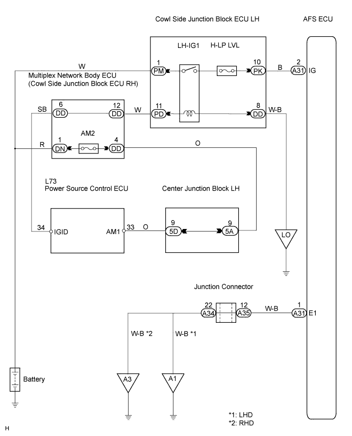
WIRING DIAGRAM
INSPECTION PROCEDURE
CHECK AFS ECU
CHECK WIRE HARNESS (AFS ECU - BODY GROUND)
LIGHTING SYSTEM - AFS ECU Power Source Circuit |
DESCRIPTION
This circuit detects the state of the engine switch. The AFS ECU receives it from the engine switch.
WIRING DIAGRAM
INSPECTION PROCEDURE
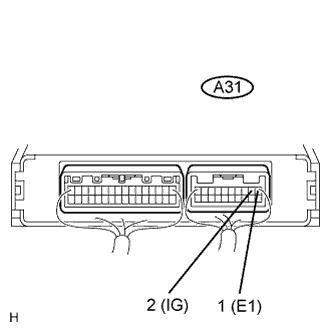
Measure the voltage of the connector.
- Standard voltage:
Tester Connection
| Condition
| Specified Condition
|
A31-1 - A31-2
| Engine switch off
| Below 1 V
|
A31-1 - A31-2
| Engine switch on (IG)
| 10 to 14 V
|
| OK |
|
|
|
| PROCEED TO NEXT CIRCUIT INSPECTION SHOWN IN PROBLEM SYMPTOMS TABLE |
|
| 2.CHECK WIRE HARNESS (AFS ECU - BODY GROUND) |
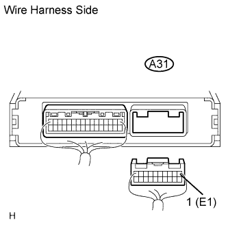
Disconnect the A31 AFS ECU connector.
Measure the resistance of the wire harness side connector.
- Standard resistance:
Tester Connection
| Condition
| Specified Condition
|
A31-1 - Body ground
| Always
| Below 1 Ω
|
| | PROCEED TO NEXT CIRCUIT INSPECTION SHOWN IN PROBLEM SYMPTOMS TABLE |
|
|
| NG |
|
|
|
| REPAIR OR REPLACE HARNESS AND CONNECTOR (AFS ECU - BODY GROUND) |
|