Lighting System Headlight Beam Level Control Actuator Circuit
Lighting. Lexus Gs430, Gs300. Uzs190 Grs190
DESCRIPTION
WIRING DIAGRAM
INSPECTION PROCEDURE
CHECK WIRE HARNESS (AFS ECU - HEADLIGHT)
INSPECT HEADLIGHT BEAM LEVEL CONTROL MOTOR
LIGHTING SYSTEM - Headlight Beam Level Control Actuator Circuit |
DESCRIPTION
The headlight level control motor receives signals from the headlight beam level control ECU to operate. The headlight beam level control ECU receives signals regarding operating conditions of the headlight beam level control motor.
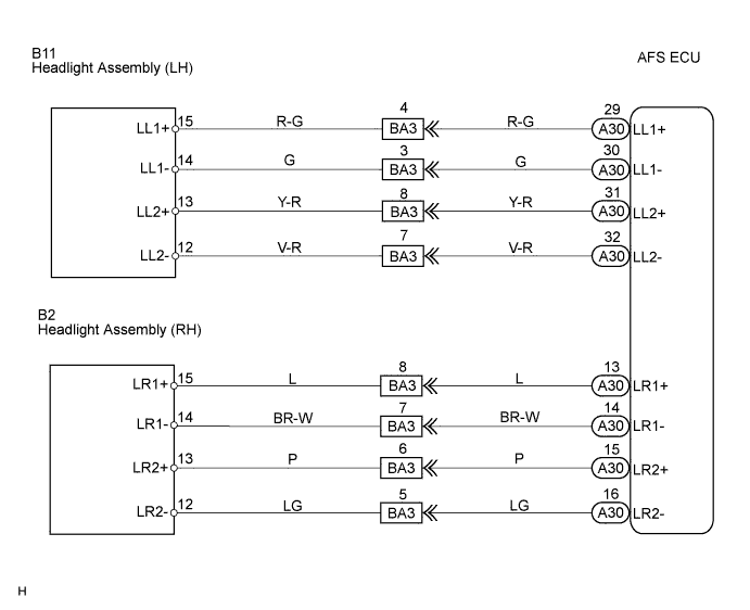
WIRING DIAGRAM
INSPECTION PROCEDURE
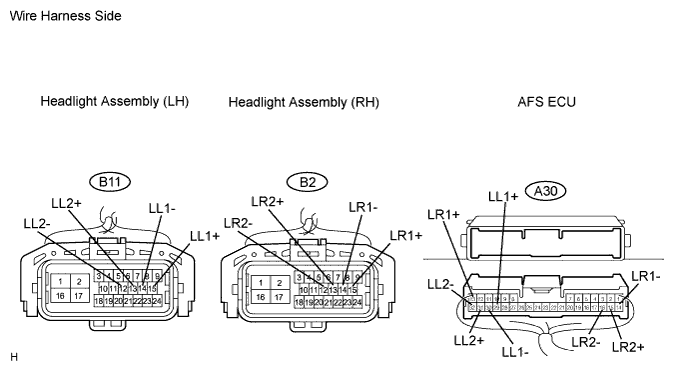
| 1.CHECK WIRE HARNESS (AFS ECU - HEADLIGHT) |
Disconnect the headlight connector on the headlight beam level control motor side and headlight beam level control ECU connector.
Measure the resistance of the wire harness side connectors.
- Standard resistance:
LH sideTester Connection
| Condition
| Specified Condition
|
A30-29 (LL1+) - B11-15 (LL1+)
| Always
| Below 1 Ω
|
A30-30 (LL1-) - B11-14 (LL1-)
| Always
| Below 1 Ω
|
A30-31 (LL2+) - B11-13 (LL2+)
| Always
| Below 1 Ω
|
A30-32 (LL2-) - B11-12 (LL2-)
| Always
| Below 1 Ω
|
A30-29 (LL1+) or B11-15 (LL1+) - Body ground
| Always
| 10 kΩ or higher
|
A30-30 (LL1-) or B11-14 (LL1-) - Body ground
| Always
| 10 kΩ or higher
|
A30-31 (LL2+) or B11-13 (LL2+) - Body ground
| Always
| 10 kΩ or higher
|
A30-32 (LL2-) or B11-12 (LL2-) - Body ground
| Always
| 10 kΩ or higher
|
RH sideTester Connection
| Condition
| Specified Condition
|
A30-13 (LR1+) - B2-15 (LR1+)
| Always
| Below 1 Ω
|
A30-14 (LR1-) - B2-14 (LR1-)
| Always
| Below 1 Ω
|
A30-15 (LR2+) - B2-13 (LR2+)
| Always
| Below 1 Ω
|
A30-16 (LR2-) - B2-12 (LR2-)
| Always
| Below 1 Ω
|
A30-13 (LR1+) or B2-15 (LR1+) - Body ground
| Always
| 10 kΩ or higher
|
A30-14 (LR1-) or B2-14 (LR1-) - Body ground
| Always
| 10 kΩ or higher
|
A30-15 (LR2+) or B2-13 (LR2+) - Body ground
| Always
| 10 kΩ or higher
|
A30-16 (LR2-) or B2-12 (LR2-) - Body ground
| Always
| 10 kΩ or higher
|
| | REPAIR OR REPLACE HARNESS AND CONNECTOR |
|
|
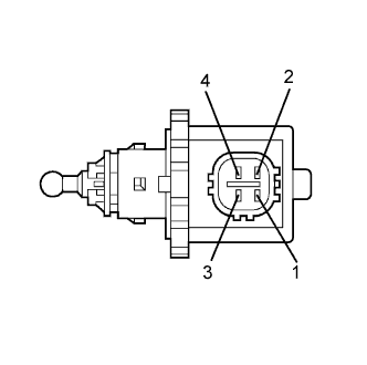
| 2.INSPECT HEADLIGHT BEAM LEVEL CONTROL MOTOR |
Measure the resistance of the motor.
- Standard resistance:
Tester Connection
| Condition
| Specified Condition
|
1 - 2
| Always
| 5.8 to 12.5 Ω
|
3 - 4
| Always
| 5.8 to 12.5 Ω
|
- HINT:
- Measure the resistance after the headlight has cooled.
| | REPLACE HEADLIGHT ASSEMBLY |
|
|
| OK |
|
|
|
| PROCEED TO NEXT CIRCUIT INSPECTION SHOWN IN PROBLEM SYMPTOMS TABLE |
|