Lighting. Lexus Gs430, Gs300. Uzs190 Grs190
DESCRIPTION
WIRING DIAGRAM
INSPECTION PROCEDURE
CHECK OPERATION OF FRONT LIGHT OR REAR LIGHT
PERFORM ACTIVE TEST BY INTELLIGENT TESTER
INSPECT FUSE (FR TAIL, FR CTRL-AM)
REPLACE CLEARANCE LIGHT BULB (LH OR RH)
CHECK WIRE HARNESS (ENGINE ROOM NO. 2 JUNCTION BLOCK - BATTERY)
CHECK WIRE HARNESS (ENGINE ROOM NO. 2 JUNCTION BLOCK - BODY GROUND)
PERFORM ACTIVE TEST BY INTELLIGENT TESTER
INSPECT FUSE (RR TAIL)
CHECK WIRE HARNESS (NO. 1 JUNCTION BLOCK - BATTERY)
CHECK WIRE HARNESS (NO. 1 JUNCTION BLOCK - LIGHT (TAIL INNER LH OR TAIL INNER RH) - BODY GROUND)
REPLACE REAR COMBINATION LIGHT (TAIL INNER LH OR TAIL INNER RH)
CHECK WIRE HARNESS (NO. 1 JUNCTION BLOCK - LIGHT (TAIL OUTER LH OR TAIL OUTER RH) - BODY GROUND)
REPLACE REAR COMBINATION LIGHT (TAIL OUTER LH OR TAIL OUTER RH)
CHECK WIRE HARNESS (NO. 1 JUNCTON BLOCK - LIGHT - BODY GROUND)
REPLACE LICENSE PLATE LIGHT
LIGHTING SYSTEM - Taillight Circuit |
DESCRIPTION
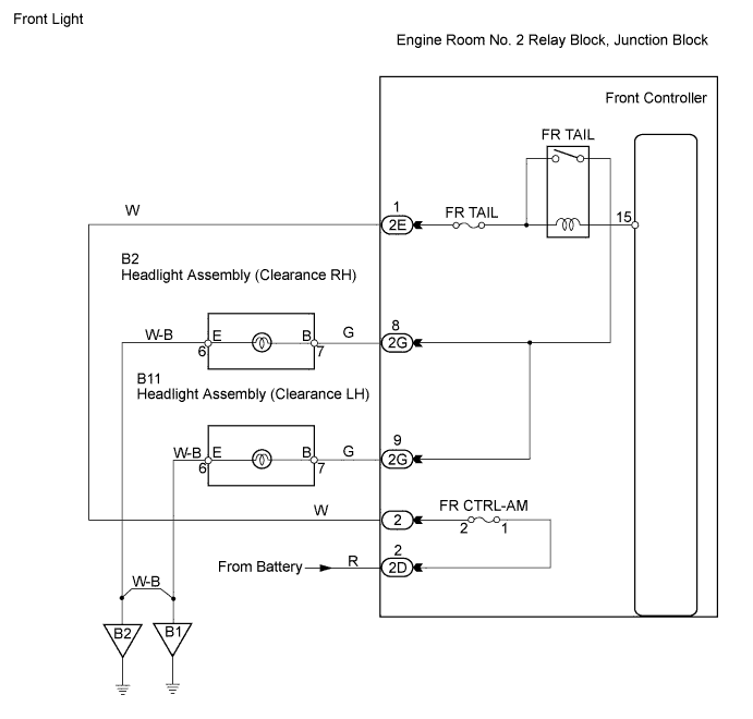
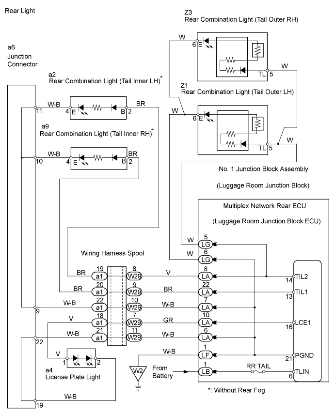
Front light: The engine room No. 2 relay block receives taillight switch information from the combination switch, and turns on the clearance light.Rear light: The multiplex network rear ECU receives taillight switch information from the combination switch, and turns on the taillights and license plate light.
WIRING DIAGRAM
INSPECTION PROCEDURE
| 1.CHECK OPERATION OF FRONT LIGHT OR REAR LIGHT |
When the taillight switch is operated, check that the following lights illuminate.
- Result:
Result
| Proceed to
|
Front lights do not illuminate
| A
|
Rear lights do not illuminate
| B
|
| 2.PERFORM ACTIVE TEST BY INTELLIGENT TESTER |
Select the Active Test, use the intelligent tester to generate a control command, and then check that the clearance light illuminates.
- Engine room No. 2 relay block:
Item
| Test Details
| Diagnostic Note
|
Clearance light operation
| Clearance light ON / OFF
| -
|
- OK:
- Light illuminates.
| OK |
|
|
|
| PROCEED TO NEXT CIRCUIT INSPECTION SHOWN IN PROBLEM SYMPTOMS TABLE |
|
| 3.INSPECT FUSE (FR TAIL, FR CTRL-AM) |
Remove the FR CTRL-AM fuse from the engine room No. 2 relay block.
Remove the FR TAIL fuse from the engine room No. 2 junction block.
Measure the resistance of the fuses.
- Standard resistance:
- Below 1 Ω
| 4.REPLACE CLEARANCE LIGHT BULB (LH OR RH) |
Temporarily replace the clearance light bulb (LH or RH) with a new or normally functioning one.
Check that the bulb illuminates.
- OK:
- Clearance light bulb illuminates.
| 5.CHECK WIRE HARNESS (ENGINE ROOM NO. 2 JUNCTION BLOCK - BATTERY) |
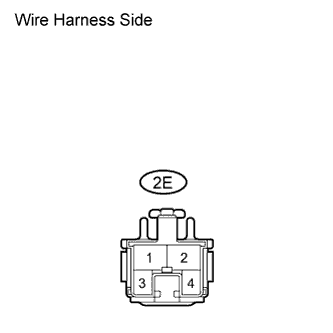
Disconnect the 2E junction block connector.
Measure the voltage of the wire harness side connector.
- Standard voltage:
Tester Connection
| Specified Condition
|
2E-1 - Body ground
| 10 to 14 V
|
| | REPAIR OR REPLACE HARNESS AND CONNECTOR |
|
|
| 6.CHECK WIRE HARNESS (ENGINE ROOM NO. 2 JUNCTION BLOCK - BODY GROUND) |
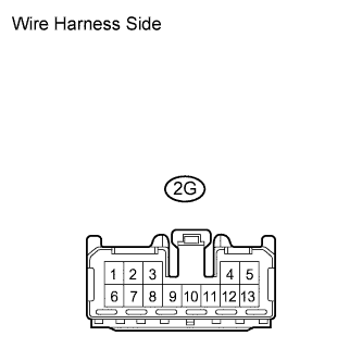
Disconnect the 2G junction block connector.
Measure the resistance of the wire harness side connector.
- Standard resistance:
Tester Connection
| Specified Condition
|
2G-8 - Body ground
| Below 1 Ω
|
2G-9 - Body ground
| Below 1 Ω
|
| | REPAIR OR REPLACE HARNESS AND CONNECTOR |
|
|
| OK |
|
|
|
| PROCEED TO NEXT CIRCUIT INSPECTION SHOWN IN PROBLEM SYMPTOMS TABLE |
|
| 7.PERFORM ACTIVE TEST BY INTELLIGENT TESTER |
Select the Active Test, use the intelligent tester to generate a control command, and then check that the taillight and license light illuminate.
- Multiplex network rear ECU:
Item
| Test Details
| Diagnostic Note
|
Tail Light
| Taillight ON / OFF
| -
|
License light
| License light ON / OFF
| -
|
- OK:
- Lights illuminate.
- Result:
Result
| Proceed to
|
OK
| A
|
All lights do not illuminate
| B
|
Taillights (inner LH or inner RH) do not illuminate*
| C
|
Taillights (outer LH or outer RH) do not illuminate
| D
|
License plate light does not illuminate
| E
|
- HINT:
- *: Without rear fog
| A |
|
|
|
| PROCEED TO NEXT CIRCUIT INSPECTION SHOWN IN PROBLEM SYMPTOMS TABLE |
|
Remove the RR TAIL fuse from the No. 1 junction block assembly.
Measure the resistance of the fuse.
- Standard resistance:
- Below 1 Ω
| 9.CHECK WIRE HARNESS (NO. 1 JUNCTION BLOCK - BATTERY) |
Disconnect the LB junction block connector.
Measure the voltage of the wire harness side connector.
- Standard voltage:
Tester Connection
| Specified Condition
|
LB-1 (TLIN) - Body ground
| 10 to 14 V
|
| | REPAIR OR REPLACE HARNESS AND CONNECTOR |
|
|
| OK |
|
|
|
| PROCEED TO NEXT CIRCUIT INSPECTION SHOWN IN PROBLEM SYMPTOMS TABLE |
|
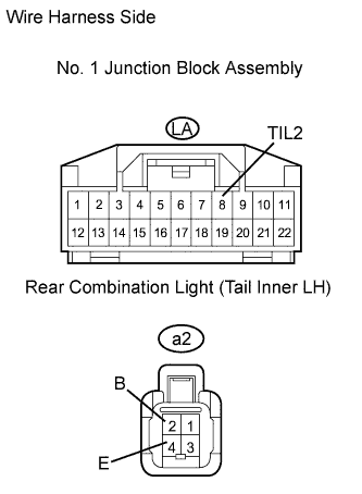
| 10.CHECK WIRE HARNESS (NO. 1 JUNCTION BLOCK - LIGHT (TAIL INNER LH OR TAIL INNER RH) - BODY GROUND) |
Check the wire harness between the rear combination light (tail inner LH) and No. 1 junction block, and the rear combination light (tail inner LH) and body ground.
Disconnect the LA junction block connector.
Disconnect the a2 combination light connector.
Measure the resistance of the wire harness side connectors.
- Standard resistance:
Tester Connection
| Specified Condition
|
LA-8 (TIL2) - a2-2 (B)
| Below 1 Ω
|
LA-8 (TIL2) or a2-2 (B) - Body ground
| 10 kΩ or higher
|
Connect the LA junction block connector.
Measure the resistance of the wire harness side connector.
- Standard resistance:
Tester Connection
| Specified Condition
|
a2-4 (E) - Body ground
| Below 1 Ω
|
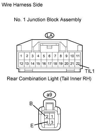
Check the wire harness between the rear combination light (tail inner RH) and No. 1 junction block, and the rear combination light (tail inner RH) and body ground.
Disconnect the LA junction block connector.
Disconnect the a9 combination light connector.
Measure the resistance of the wire harness side connectors.
- Standard resistance:
Tester Connection
| Specified Condition
|
LA-22 (TIL1) - a9-2 (B)
| Below 1 Ω
|
LA-22 (TIL1) or a9-2 (B) - Body ground
| 10 kΩ or higher
|
Connect the LA junction block connector.
Measure the resistance of the wire harness side connector.
- Standard resistance:
Tester Connection
| Specified Condition
|
a9-4 (E) - Body ground
| Below 1 Ω
|
| | REPAIR OR REPLACE HARNESS AND CONNECTOR |
|
|
| 11.REPLACE REAR COMBINATION LIGHT (TAIL INNER LH OR TAIL INNER RH) |
Temporarily replace the rear combination light (tail inner LH or tail inner RH) with a new or normally functioning one.
Check that the rear combination light illuminates.
- OK:
- Light illuminates.
| NG |
|
|
|
| PROCEED TO NEXT CIRCUIT INSPECTION SHOWN IN PROBLEM SYMPTOMS TABLE |
|
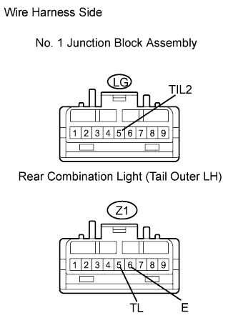
| 12.CHECK WIRE HARNESS (NO. 1 JUNCTION BLOCK - LIGHT (TAIL OUTER LH OR TAIL OUTER RH) - BODY GROUND) |
Check the wire harness between the rear combination light (tail outer LH) and No. 1 junction block, and the rear combination light (tail outer LH) and body ground.
Disconnect the LG junction block connector.
Disconnect the Z1 combination light connector.
Measure the resistance of the wire harness side connectors.
- Standard resistance:
Tester Connection
| Specified Condition
|
LG-5 (TIL2) - Z1-5 (TL)
| Below 1 Ω
|
LG-5 (TIL2) or Z1-5 (TL) - Body ground
| 10 kΩ or higher
|
Connect the LG junction block connector.
Measure the resistance of the wire harness side connector.
- Standard resistance:
Tester Connection
| Specified Condition
|
Z1-6 (E) - Body ground
| Below 1 Ω
|
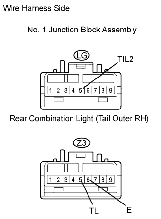
Check the wire harness between the rear combination light (tail outer RH) and No. 1 junction block, and the rear combination light (tail outer RH) and body ground.
Disconnect the LG junction block connector.
Disconnect the Z3 combination light connector.
Measure the resistance of the wire harness side connectors.
- Standard resistance:
Tester Connection
| Specified Condition
|
LG-5 (TIL2) - Z3-5 (TL)
| Below 1 Ω
|
LG-5 (TIL2) or Z3-5 (TL) - Body ground
| 10 kΩ or higher
|
Connect the LG junction block connector.
Measure the resistance of the wire harness side connector.
- Standard resistance:
Tester Connection
| Specified Condition
|
Z3-6 (E) - Body ground
| Below 1 Ω
|
| | REPAIR OR REPLACE HARNESS AND CONNECTOR |
|
|
| 13.REPLACE REAR COMBINATION LIGHT (TAIL OUTER LH OR TAIL OUTER RH) |
Temporarily replace the rear combination light (tail outer LH or tail outer RH) with a new or normally functioning one.
Check that the rear combination light illuminates.
- OK:
- Light illuminates.
| NG |
|
|
|
| PROCEED TO NEXT CIRCUIT INSPECTION SHOWN IN PROBLEM SYMPTOMS TABLE |
|
| 14.CHECK WIRE HARNESS (NO. 1 JUNCTON BLOCK - LIGHT - BODY GROUND) |
Disconnect the LA junction block connector.
Disconnect the a4 license light connector.
Measure the resistance of the wire harness side connectors.
- Standard resistance:
Tester Connection
| Specified Condition
|
LA-10 (LCE1) - a4-1
| Below 1 Ω
|
LA-10 (LCE1) or a4-1 - Body ground
| 10 kΩ or higher
|
Connect the LA junction block connector.
Measure the resistance of the wire harness side connector.
- Standard resistance:
Tester Connection
| Specified Condition
|
a4-2 - Body ground
| Below 1 Ω
|
| | REPAIR OR REPLACE HARNESS AND CONNECTOR |
|
|
| 15.REPLACE LICENSE PLATE LIGHT |
Temporarily replace the license plate light with a new or normally functioning one.
Check that the light illuminates.
- OK:
- Light illuminates.
| NG |
|
|
|
| PROCEED TO NEXT CIRCUIT INSPECTION SHOWN IN PROBLEM SYMPTOMS TABLE |
|