Theft Deterrent System Ig Power Source Circuit
DESCRIPTION
WIRING DIAGRAM
INSPECTION PROCEDURE
CHECK BASIC FUNCTION (ENTRY AND START FUNCTION)
INSPECT FUSE (AM2, ECU-IG RH)
CHECK WIRE HARNESS (COWL SIDE JUNCTION BLOCK RH - BATTERY)
CHECK COWL SIDE JUNCTION BLOCK RH
CHECK WIRE HARNESS (COWL SIDE JUNCTION BLOCK RH - BODY GROUND)
CHECK WIRE HARNESS (COWL SIDE JUNCTION BLOCK RH - POWER SOURCE CONTROL ECU)
THEFT DETERRENT SYSTEM - IG Power Source Circuit |
DESCRIPTION
- When the engine switch is turned on (IG), positive (+) battery voltage is applied to the cowl side junction block RH (multiplex network body ECU).
WIRING DIAGRAM
INSPECTION PROCEDURE
| 1.CHECK BASIC FUNCTION (ENTRY AND START FUNCTION) |
Check that the basic function of the entry and start system operates normally.
- OK:
- Basic function operates normally.
| | Go to ENTRY AND START SYSTEM |
|
|
| 2.INSPECT FUSE (AM2, ECU-IG RH) |
Remove the AM2 and ECU-IG RH fuses from the cowl side junction block.
Measure the resistance of the fuses.
- Standard resistance:
- Below 1 Ω
| 3.CHECK WIRE HARNESS (COWL SIDE JUNCTION BLOCK RH - BATTERY) |
Disconnect the DM junction block connector.
Measure the voltage of the wire harness side connector.
- Standard voltage:
Tester Connection
| Specified Condition
|
DM-1 - Body ground
| 10 to 14 V
|
| | REPAIR OR REPLACE HARNESS AND CONNECTOR |
|
|
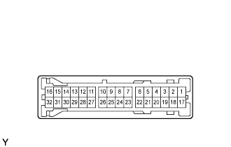
| 4.CHECK COWL SIDE JUNCTION BLOCK RH |
Measure the voltage between the terminal of the connector and body ground.
- Standard voltage:
Tester Connection
| Specified Condition
|
DD-4 - Body ground
| 10 to 14 V
|
| | REPLACE COWL SIDE JUNCTION BLOCK RH |
|
|
| 5.CHECK WIRE HARNESS (COWL SIDE JUNCTION BLOCK RH - BODY GROUND) |
Disconnect the DD junction block connector.
Measure the resistance of the wire harness side connector.
- Standard resistance:
Tester Connection
| Specified Condition
|
DD-7 - Body ground
| Below 1 Ω
|
| | REPAIR OR REPLACE HARNESS AND CONNECTOR |
|
|
| 6.CHECK WIRE HARNESS (COWL SIDE JUNCTION BLOCK RH - POWER SOURCE CONTROL ECU) |
Disconnect the DD junction block connector.
Disconnect the L73 ECU connector.
Measure the resistance of the wire harness side connectors.
- Standard resistance:
Tester Connection
| Specified Condition
|
DD-4 - L73-33 (AM1)
| Below 1 Ω
|
DD-6 - L73-34 (IG1D)
| Below 1 Ω
|
DD-4 or L73-33 (AM1) - Body ground
| 10 kΩ or higher
|
DD-6 or L73-34 (IG1D) - Body ground
| 10 kΩ or higher
|
| | REPAIR OR REPLACE HARNESS AND CONNECTOR |
|
|
| OK |
|
|
|
| PROCEED TO NEXT CIRCUIT INSPECTION SHOWN IN PROBLEM SYMPTOMS TABLE PUSH-BUTTON START SYSTEM |
|