Theft Deterrent System Ecu Power Source Circuit
DESCRIPTION
WIRING DIAGRAM
INSPECTION PROCEDURE
INSPECT FUSE (D/C CUT, MPX-B)
CHECK WIRE HARNESS (COWL SIDE JUNCTION BLOCK RH - BATTERY AND BODY GROUND)
THEFT DETERRENT SYSTEM - ECU Power Source Circuit |
DESCRIPTION
- This circuit provides power to operate the cowl side junction block (multiplex network body ECU).
WIRING DIAGRAM
INSPECTION PROCEDURE
| 1.INSPECT FUSE (D/C CUT, MPX-B) |
Remove the D/C CUT and MPX-B fuses from the engine room No. 1 junction block.
Measure the resistance of the fuses.
- Standard resistance:
- Below 1 Ω
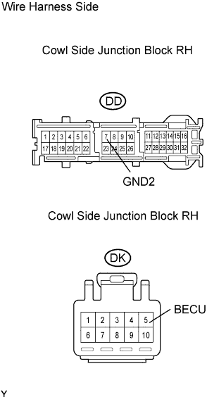
| 2.CHECK WIRE HARNESS (COWL SIDE JUNCTION BLOCK RH - BATTERY AND BODY GROUND) |
Disconnect the DD and DK junction block connectors.
Measure the voltage and resistance of the wire harness side connectors.
- Standard voltage:
Tester Connection
| Specified Condition
|
DK-5 (BECU) - Body ground
| 10 to 14 V
|
- Standard resistance:
Tester Connection
| Specified Condition
|
DD-7 (GND2) - Body ground
| Below 1 Ω
|
| | REPAIR OR REPLACE HARNESS AND CONNECTOR |
|
|
| OK |
|
|
|
| REPLACE COWL SIDE JUNCTION BLOCK RH (MULTIPLEX NETWORK BODY ECU) |
|