Securities. Lexus Gs430, Gs300. Uzs190 Grs190
Theft Deterrent. Lexus Gs430, Gs300. Uzs190 Grs190
Theft Deterrent System -- Terminals Of Ecu |
| CHECK COWL SIDE JUNCTION BLOCK RH (MULTIPLEX NETWORK BODY ECU) |
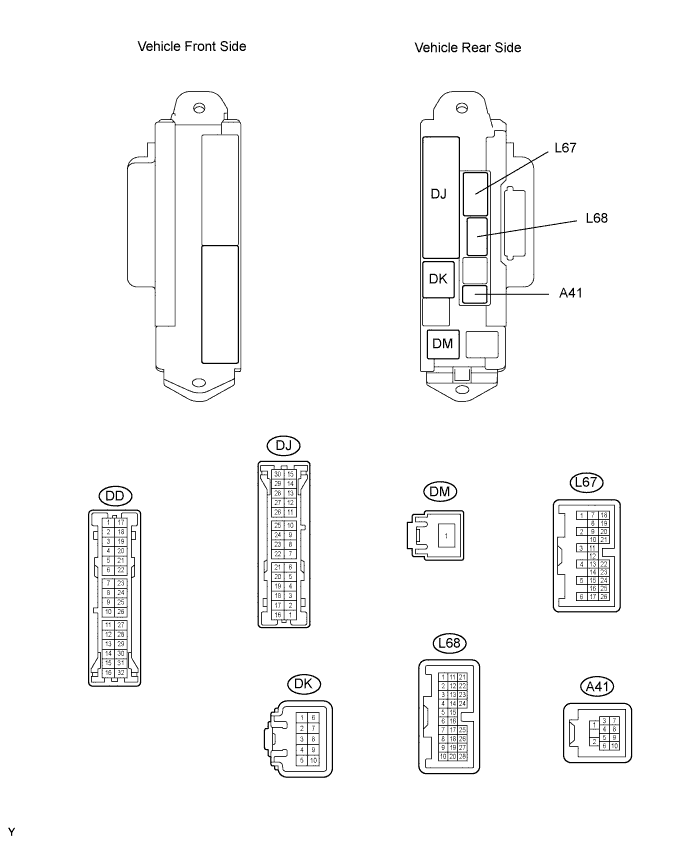
Disconnect the DD, DK, DJ and DM junction block connectors.
Measure the voltage and resistance of the wire harness side connectors.
If the result is not as specified, there may be a malfunction on the wire harness side.Symbols (Terminal No.) Wiring Color Terminal Description Condition Specified Condition GND2 (DD-7) - Body ground W-B - Body ground Ground Always Below 1 Ω BECU (DK-5) - Body ground G-R - Body ground Battery (power supply) Always 10 to 14 V BATB (DJ-5) - Body ground O - Body ground Battery (power supply) Always 10 to 14 V IG (DM-1) - Body ground B - Body ground Ignition power supply Always 10 to 14 V Reconnect the DD, DK, DJ and DM junction block connectors.
Measure the voltage of the connector.
Symbols (Terminal No.) Wiring Color Terminal Description Condition Specified Condition IND (L67-24) - Body ground LG - Body ground Security indicator signal Security indicator illuminates or blinks when system is in armed state 3 to 6 V SH (A41-1) - Body ground*1 W - Body ground Security horn signal Security horn is sounding (Theft deterrent system is in alarm sounding state) Pulse generation HAZ (L67-2) - Body ground O - Body ground Hazard warning light signal System is in alarm sounding state Pulse generation SSCL (L67-12) - Body ground*2 G - Body ground Theft warning siren signal Theft warning siren is sounding (Theft warning system is in alarm sounding state) Pulse generation - HINT:
- *1: Countries other than Europe, Russia, Turkey and China
- *2: Europe, Russia, Turkey and China
| CHECK ENGINE ROOM NO. 2 RELAY BLOCK, JUNCTION BLOCK (FRONT CONTROLLER) |
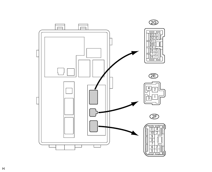
Disconnect the 2E, 2F and 2G front controller connectors.
Measure the voltage and resistance of the wire harness side connectors.
If the result is not as specified, there may be a malfunction on the wire harness side.Symbols (Terminal No.) Wiring Color Terminal Description Condition Specified Condition 2E-4 - Body ground G-R - Body ground Battery power supply (ECU) Always 10 to 14 V 2F-1 - Body ground W-B - Body ground Ground Always Below 1 Ω 2G-3 - Body ground W-L - Body ground Engine hood courtesy switch signal Engine hood closed 10 kΩ or higher 2G-3 - Body ground W-L - Body ground Engine hood courtesy switch signal Engine hood open Below 1 Ω Reconnect the 2E, 2F and 2G front controller connectors.
Measure the voltage of the connector.
If the result is not as specified, the junction block may have a malfunction.Symbols (Terminal No.) Wiring Color Terminal Description Condition Specified Condition 2G-1 - Body ground B - Body ground Horn signal Horn sounding 10 to 14 V 2G-1 - Body ground B - Body ground Horn signal Horn sounding Below 1 V
| CHECK POWER SOURCE CONTROL ECU ASSEMBLY |

Disconnect the L73 ECU connector.
Measure the resistance and voltage of the wire harness side connector.
If the result is not as specified, there may be a malfunction on the wire harness side.Symbols (Terminal No.) Wiring Color Terminal Description Condition Specified Condition AM1 (L73-33) - Body ground R - Body ground +B power supply Always 10 to 14 V AM2 (L73-12) - Body ground O - Body ground +B power supply Always 10 to 14 V GND2 (L73-6) - Body ground W-B - Body ground Ground Always Below 1 Ω