Dtc B1651/33 Manual Cut Off Switch Trouble
DESCRIPTION
WIRING DIAGRAM
INSPECTION PROCEDURE
CHECK INSTRUMENT PANEL WIRE (OPEN)
CHECK INSTRUMENT PANEL WIRE (SHORT)
CHECK INSTRUMENT PANEL WIRE (SHORT TO GROUND)
CHECK INSTRUMENT PANEL WIRE (SHORT TO B+)
CHECK AIRBAG CUT OFF SWITCH CYLINDER
CHECK CENTER AIRBAG SENSOR ASSEMBLY
DTC B1651/33 Manual Cut off Switch Trouble |
DESCRIPTION
The manual cut off switch circuit consists of the center airbag sensor assembly ad the airbag cut off switch cylinder.The front passenger airbag assembly can be optionally deactivated via this circuit by turning the manual cut off switch to the OFF position.If the front passenger airbag assembly is deactivated, the passenger airbag OFF indicator comes on to inform the passengers.DTC B1651/33 is recorded when a malfunction is detected in the manual cut off switch circuit.DTC No.
| DTC Detecting Condition
| Trouble Area
|
B1651/33
| - The center airbag sensor assembly receives a line short circuit signal, an open circuit signal, a short circuit to ground signal or a short circuit to B+ signal in the manual cut off switch circuit for 2 seconds.
- Manual cut off switch malfunction
- Center airbag sensor assembly malfunction
| - Instrument panel wire
- Airbag cut off switch cylinder
- Center airbag sensor assembly
|
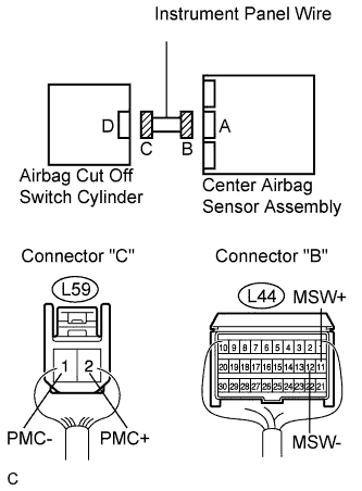
WIRING DIAGRAM
INSPECTION PROCEDURE
- HINT:
- The "B" L78-11 (MSW+) and L78-12 (MSW-) connectors in this circuit have an activation prevention mechanism.
- This mechanism can be used to check for an open circuit in the wire harness. In case of other checks (check for short, short to ground or short to B+), this mechanism should be released.
| 1.CHECK INSTRUMENT PANEL WIRE (OPEN) |
Turn the engine switch off.
Disconnect the negative (-) terminal cable from the battery, and wait for at least 90 seconds.
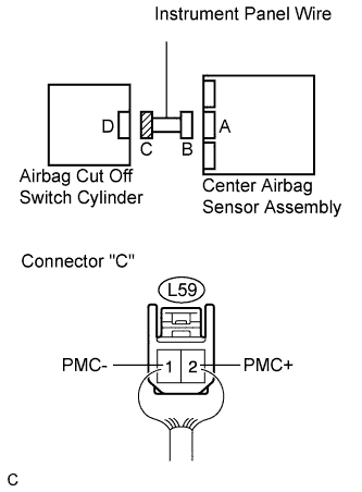
Disconnect the connectors from the center airbag sensor assembly and the airbag cut off switch cylinder.
Measure the resistance according to the value(s) in the table below.
- Resistance:
Tester connection
| Condition
| Specified condition
|
L59-2 (PMC+) -
L59-1 (PMC-)
| Always
| Below 1 Ω
|
| | REPAIR OR REPLACE INSTRUMENT PANEL WIRE |
|
|
| 2.CHECK INSTRUMENT PANEL WIRE (SHORT) |
Release the activation prevention mechanism built into connector "B".
Measure the resistance according to the value(s) in the table below.
- Resistance:
Tester connection
| Condition
| Specified condition
|
L59-2 (PMC+) -
L59-1 (PMC-)
| Always
| 1 MΩ or higher
|
| | REPAIR OR REPLACE INSTRUMENT PANEL WIRE |
|
|
| 3.CHECK INSTRUMENT PANEL WIRE (SHORT TO GROUND) |
Measure the resistance according to the value(s) in the table below.
- Resistance:
Tester connection
| Condition
| Specified condition
|
L59-2 (PMC+) -
Body ground
| Always
| 1 MΩ or higher
|
L59-1 (PMC-) -
Body ground
| Always
| 1 MΩ or higher
|
| | REPAIR OR REPLACE INSTRUMENT PANEL WIRE |
|
|
| 4.CHECK INSTRUMENT PANEL WIRE (SHORT TO B+) |
Connect the negative (-) terminal cable to the battery, and wait for at least 2 seconds.
Turn the engine switch on (IG).
Measure the voltage according to the value(s) in the table below.
- Voltage:
Tester connection
| Condition
| Specified condition
|
L59-2 (PMC+) -
Body ground
| Engine switch on (IG)
| Below 1 V
|
L59-1 (PMC-) -
Body ground
| Engine switch on (IG)
| Below 1 V
|
| | REPAIR OR REPLACE INSTRUMENT PANEL WIRE |
|
|
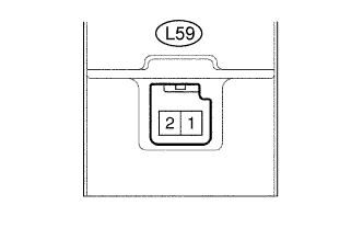
| 5.CHECK AIRBAG CUT OFF SWITCH CYLINDER |
Turn the engine switch off.
Disconnect the negative (-) terminal cable from the battery, and wait for at least 90 seconds.
Measure the resistance according to the value(s) in the table below.
- Resistance:
Tester connection
| Manual cut off switch condition
| Specified condition
|
L59-2 (PMC+) -
L59-1 (PMC-)
| Cut off switch is in ON position (Front passenger side airbag is active)
| 360 to 440 Ω
|
L59-2 (PMC+) -
L59-1 (PMC-)
| Cut off switch is in OFF position (Front passenger side airbag is not active)
| 90 to 110 Ω
|
| | REPLACE AIRBAG CUT OFF SWITCH CYLINDER |
|
|
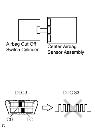
| 6.CHECK CENTER AIRBAG SENSOR ASSEMBLY |
Connect the connectors to the center airbag sensor assembly and the airbag cut off switch cylinder.
Connect the negative (-) terminal cable to the battery, and wait for at least 2 seconds.
Turn the engine switch on (IG), and wait for at least 60 seconds.
Clear the DTCs stored in memory (Click here).
Turn the engine switch off.
Turn the engine switch on (IG), and wait for at least 60 seconds.
Check the DTCs (Click here).
- OK:
- DTC B1651/33 is not output.
- HINT:
- Codes other than DTC B1651/33 may be output at this time, but they are not related to this check.
| | REPLACE CENTER AIRBAG SENSOR ASSEMBLY |
|
|
| OK |
|
|
|
| USE SIMULATION METHOD TO CHECK |
|