Air Conditioning System Air Conditioning Compressor Magnetic Clutch Circuit
DESCRIPTION
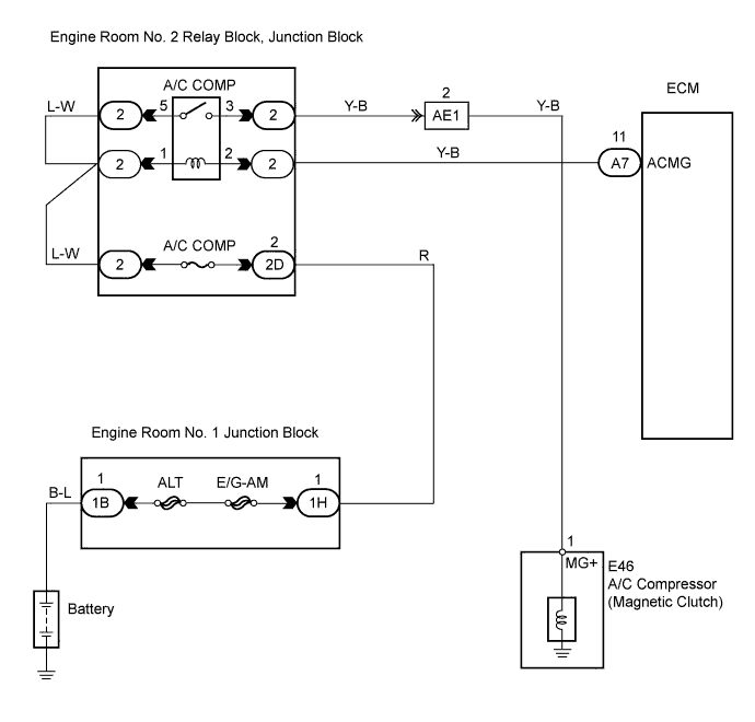
WIRING DIAGRAM
INSPECTION PROCEDURE
INSPECT FUSE (A/C COMP)
READ VALUE OF INTELLIGENT TESTER
PERFORM ACTIVE TEST BY INTELLIGENT TESTER
INSPECT RELAY (A/C COMP)
INSPECT A/C COMPRESSOR
CHECK WIRE HARNESS (ENGINE ROOM NO. 2 RELAY BLOCK - A/C COMPRESSOR)
CHECK WIRE HARNESS (ENGINE ROOM NO. 2 RELAY BLOCK - ECM)
AIR CONDITIONING SYSTEM - Air Conditioning Compressor Magnetic Clutch Circuit |
DESCRIPTION
The A/C amplifier sends a magnetic clutch ON command signal to the ECM through the BEAN line and CAN line. Then the ECM turns the A/C COMP relay on to turn the magnetic clutch on.
WIRING DIAGRAM
INSPECTION PROCEDURE
| 1.INSPECT FUSE (A/C COMP) |
Remove the A/C COMP fuse from the engine room No. 2 junction block.
Measure the resistance of the fuse.
- Standard resistance:
Tester Item
| Condition
| Specified Condition
|
A/C COMP fuse
| Always
| Below 1 Ω
|
| 2.READ VALUE OF INTELLIGENT TESTER |
Connect the intelligent tester to the DLC3.
Turn the engine switch on (IG) and push the intelligent tester main switch on.
Select the item below in the Data List, and read the displays on the intelligent tester.
ECM:Item
| Measurement Item / Display
(Range)
| Normal Condition
| Diagnostic Note
|
A/C Magnetic Clutch Relay
(A/C Mag Clutch)
| A/C Magnetic Clutch Relay / OFF, ON
| ON: A/C magnetic clutch ON
OFF: A/C magnetic clutch OFF
| -
|
- OK:
- The display is the condition.
| 3.PERFORM ACTIVE TEST BY INTELLIGENT TESTER |
Select the item below in the Active Test, and read the displays on the intelligent tester.
A/C amplifier:Item
| Test Details / Display
(Range)
| Diagnostic Note
|
Magnetic Clutch Relay
(A/C Mag Clutch)
| Magnetic Clutch Relay / OFF, ON
| -
|
| 4.INSPECT RELAY (A/C COMP) |
Remove the A/C COMP relay from the engine room No. 2 relay block.
Measure the resistance of the relay.
- Standard resistance:
Tester Connection
| Specified Condition
|
3 - 5
| 10 kΩ or higher
|
3 - 5
| Below 1 Ω
(when battery voltage is applied to terminals 1 and 2)
|
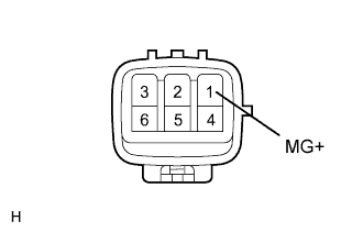
Disconnect the E46 A/C compressor connector.
Measure the resistance of the connector.
- Standard resistance:
Tester Connection
| Condition
| Specified Condition
|
1 (MG+) - Body ground
| Always
| Below 1 Ω
|
When connector terminal 1 (MG+) is connected to the positive (+) battery terminal, and the body ground is connected to the negative (-) battery terminal, check that the following occurs: 1) the magnetic clutch's operating sound is emitted, and 2) the magnetic clutch's hub and rotor lock.
| 6.CHECK WIRE HARNESS (ENGINE ROOM NO. 2 RELAY BLOCK - A/C COMPRESSOR) |
Remove the A/C COMP relay from the engine room No. 2 relay block.
Disconnect the E46 A/C compressor connector.
Measure the resistance of the wire harness side connector.
- Standard resistance:
Tester Connection
| Specified Condition
|
Relay block A/C COMP relay terminal 3- E46-1 (MG+)
| Below 1 Ω
|
| | REPAIR OR REPLACE HARNESS AND CONNECTOR |
|
|
| 7.CHECK WIRE HARNESS (ENGINE ROOM NO. 2 RELAY BLOCK - ECM) |
Remove the A/C COMP relay from the engine room No. 2 relay block.
Disconnect the A7 ECM connector.
Measure the resistance of the wire harness side connectors.
- Standard resistance:
Tester Connection
| Specified Condition
|
Relay block A/C COMP relay terminal 2 - A7-11 (ACMG)
| Below 1 Ω
|
| | REPAIR OR REPLACE HARNESS AND CONNECTOR |
|
|
| OK |
|
|
|
| PROCEED TO NEXT CIRCUIT INSPECTION SHOWN IN PROBLEM SYMPTOMS TABLE |
|