Air Conditioning System Check Mode Procedure
LIST OF OPERATION METHODS
CHECK DLC3
Air Conditioning System -- Check Mode Procedure |
| LIST OF OPERATION METHODS |
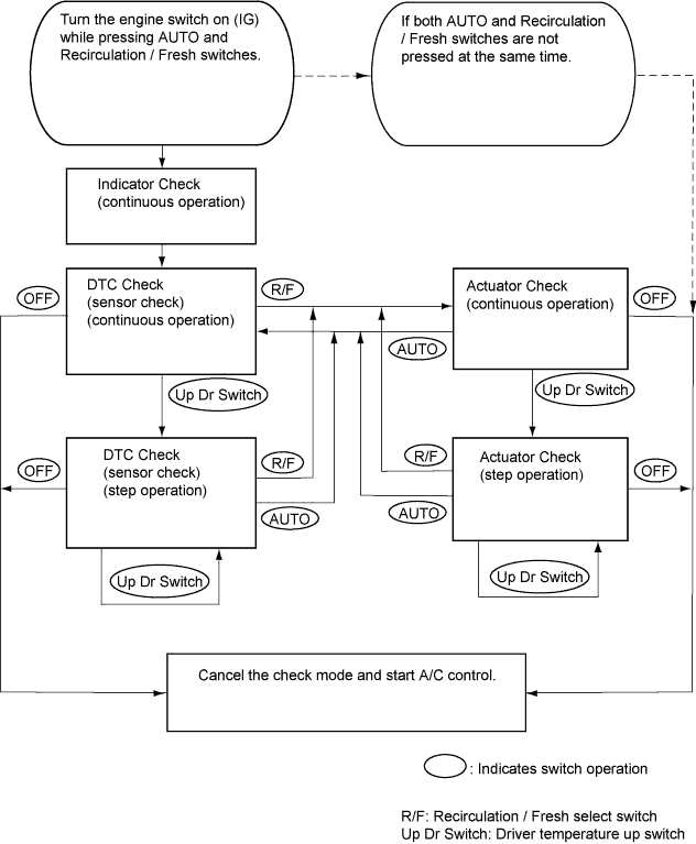
By operating each of the A/C control switches as shown in the diagram below, it is possible to enter the diagnostic check mode.
The vehicle uses the ISO 15765-4 communication protocol. The terminal arrangement of the DLC3 complies with ISO 15031-03 and matches the ISO 15765-4 format.
- HINT:
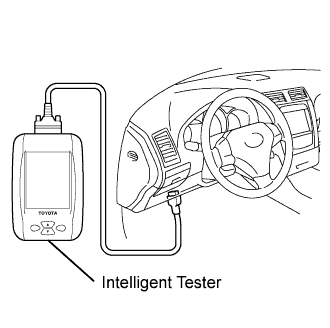
- Connect the cable of the intelligent tester to the DLC3, turn the engine switch on (IG) and attempt to use the tester. If the display indicates that a communication error has occurred, there is a problem either with the vehicle or with the tester.
- If communication is normal when the tester is connected to another vehicle, inspect the DLC3 of the original vehicle.
- If communication is still not possible when the tester is connected to another vehicle, the problem may be in the tester itself. Consult the Service Department listed in the tester's instruction manual.
Symbol
(Terminal No.)
| Terminal Description
| Condition
| Specified Condition
|
SIL (7) - SG (5)
| Bus "+" line
| During transmission
| Pulse generation
|
CG (4) - Body ground
| Chassis ground
| Always
| Below 1 Ω
|
SG (5) - Body ground
| Signal ground
| Always
| Below 1 Ω
|
BAT (16) - Body ground
| Battery positive
| Always
| 11 to 14 V
|
CANH (6) - CANL (14)
| HIGH-level CAN bus line
| Engine switch off
| 54 to 67 Ω
|
CANH (6) - Battery positive
| HIGH-level CAN bus line
| Engine switch off
| 1 MΩ or higher
|
CANH (6) - CG (4)
| HIGH-level CAN bus line
| Engine switch off
| 3 MΩ or higher
|
CANL (14) - Battery positive
| LOW-level CAN bus line
| Engine switch off
| 1 MΩ or higher
|
CANL (14) - CG (4)
| LOW-level CAN bus line
| Engine switch off
| 3 MΩ or higher
|