Heater & Air Conditioning System. Lexus Gs430, Gs300. Uzs190 Grs190
Air Conditioning. Lexus Gs430, Gs300. Uzs190 Grs190
Air Conditioning System -- System Description |
| GENERAL |
The air conditioning system has the following features:
- In compliance with the temperature set with the temperature control switch, the A/C amplifier calculates the outlet temperature based on the input signals from various sensors. In addition, corrections in accordance with the signals from the room humidity sensor and the water temperature sensor are added to control the outlet air temperature.
- Controls the blower motor in accordance with the airflow volume that has been calculated by A/C amplifier based on the input signals from various sensors.
- Automatically changes the outlets in accordance with the outlet mode ratio that has been calculated by the A/C amplifier based on the input signals from various sensors.
- Automatically controls the air inlet control damper in accordance with the airflow volume that has been calculated by the A/C amplifier.
- Based on the signals from the ambient temperature sensor, this control calculates the outside temperature, which is then corrected in the air conditioning amplifier, and shown in the multi-information display in the combination meter.
- Turns the rear defogger and outside rear mirror heaters on for 15 minutes when the rear defogger switch is pressed. Turns them off if the switch is pressed while they are operating.
- The A/C amplifier automatically controls the air inlets based on the signals from the smog ventilation sensor.
- Checks the sensors in accordance with operation of the air conditioner switches.
- HINT:
- The smart connector has a built-in IC that enables communication with the A/C amplifier and servomotor driving and position detection.
- The A/C amplifier is equipped with the function of controlling the indicator lighting.
- In compliance with the temperature set with the temperature control switch, the A/C amplifier calculates the outlet temperature based on the input signals from various sensors. In addition, corrections in accordance with the signals from the room humidity sensor and the water temperature sensor are added to control the outlet air temperature.
| MODEL POSITION AND DAMPER OPERATION |
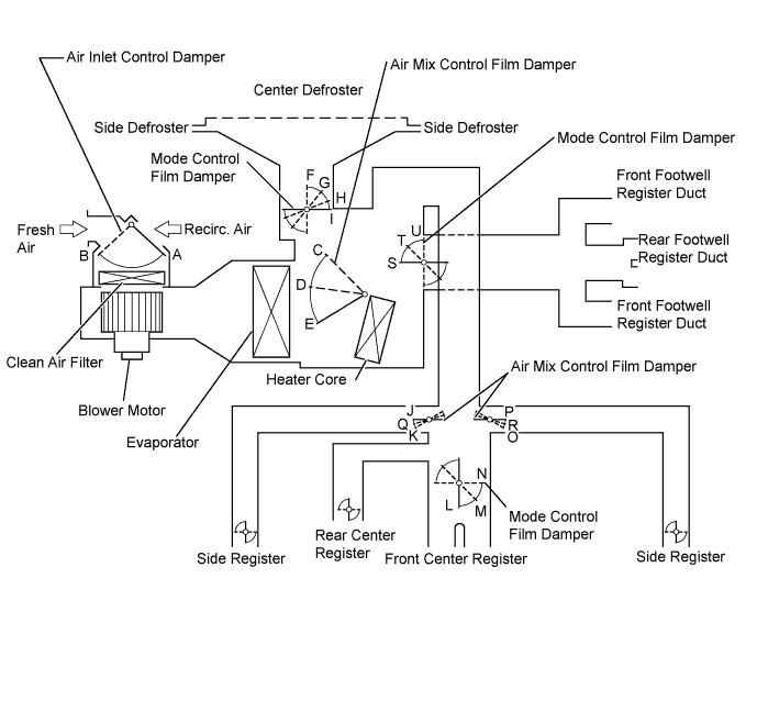
| Control Damper | Control Position | Damper Position | Operation | ||
| Air Inlet Control Damper | FRESH | B | Brings in fresh air. | ||
| RECIRC | A | Recirculates internal air. | |||
| Air Mix Control Film Damper | Driver and Front Passenger Side | MAX COOL to MAX HOT (TEMP. SETTING 18 to 32°C (64 to 90°F)) | C, D, E | Varies the mixture ratio of the fresh air and the recirculation air in order to regulate the temperature continuously from HOT to COOL. | |
| Mode Control Film Damper | Driver and Front Passenger Side |  FACE | I, J, L, P, U | Air blows out of the front and rear center registers, and side registers. *1 | |
 BI - LEVEL | I, Q, M, R, T | Air mainly blows out of the front and rear center registers, side registers, and footwell register ducts. | |||
 FOOT | H, K, N, O, S | Air mainly blows out of the front and rear footwell register ducts. In addition, air blows out slightly from the front and side defrosters, and the side registers. *2 | |||
 FOOT / DEF | G, K, N, O, T | Air mainly blows out of the front and side defrosters to defrost the windshield. Air also blows out from the front and rear footwell register ducts, and the side registers. *2 | |||
 DEF | F, K, N, O, U | Air blows out of the front and side defrosters and side registers to defrost the windshield. | |||
*2: In the multi mode, air blows out of all the air outlets.
| AIR OUTLETS AND AIRFLOW VOLUME |

| Air Outlet Mode | Selectable Mode | Register | ||||||
| Driver | Passenger | Rear | ||||||
| Automatic | Manual | Center | Side | Center | Side | Center | ||
| FACE U |  | |  | | | | |
| FACE L | |  |  | | | | | |
| B/L U | | | | | | | |
| B/L L | | | | | | | | |
| FOOT (DEF=0) | | | | | | | |
| FOOT D | | | | | | | | |
| FOOT R | | | | | | | | |
| FOOT F | | | | | | | | |
| F/D | | | | | | | |
| DEF | | | - | - | - | - | - |
| Air Outlet Position Symbol | A | B | C | D | E | |||
| Air Outlet Mode | Footwell | Defroster | |||||||
| Driver | Passenger | Driver | Passenger | ||||||
| Front | Rear | Front | Rear | Front | Side | Front | Side | ||
| FACE U | - | - | - | - | - | - | - | - |
| FACE L | | | | | - | - | - | - | |
| B/L U |  | | | | - | - | - | - |
| B/L L | | | | | - | - | - | - | |
| FOOT (DEF=0) | | | | | - | - | - | - |
| FOOT D | | | | | | | | | |
| FOOT R | | | | | | | | | |
| FOOT F | | | | | | | | | |
| F/D | | | | | | | | |
| DEF | - | - | - | - | | | | |
| Air Outlet Position Symbol | F | G | H | I | J | K | L | M | |
- HINT:
- The size of the circle indicates the proportion of airflow volume. There are 4 sizes.