Variable Gear Ratio Steering System -- Diagnosis System |
| DIAGNOSTIC SYSTEM |
Inspect the battery voltage.
- Standard:
- 11 to 14 V
- HINT:
- If the voltage is below 11 V, recharge the battery before proceeding.
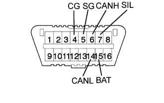
Check the DLC3.
The steering control ECU uses CAN and ISO 9141-2 as its communication protocol. The terminal arrangement of the DLC3 complies with ISO 15031-3and matches the ISO 9141-2 format. Verify the conditions listed in the table below.
Symbols (Terminals No.) Terminal description Condition Specified condition SIL (7) - SG (5) Bus "+" line During transmission Pulse generation CG (4) - Body ground Chassis ground Always Below 1 Ω SG (5) - Body ground Signal ground Always Below 1 Ω BAT (16) - Body ground Battery positive Always 11 to 14 V CANH (6) - CANL (14) HIGH-level CAN bus line Engine switch off 54 to 67 Ω CANH (6) - Battery positive HIGH-level CAN bus line Engine switch off 1 MΩ or higher CANH (6) - CG (4) HIGH-level CAN bus line Engine switch off 3 kΩ or higher CANL (14) - Battery positive LOW-level CAN bus line Engine switch off 1 MΩ or higher CANL (14) - CG (4) LOW-level CAN bus line Engine switch off 3 kΩ or higher - HINT:
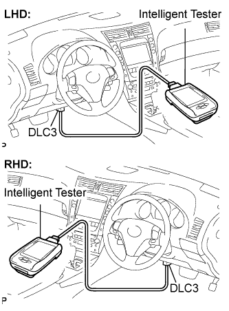
- If the display shows a communication error message when you connect the cable of the intelligent tester to the DLC3, turn the engine switch on (IG) and operate the intelligent tester, there is a problem on either the vehicle side or the tool side.
- If communication is normal when the tool is connected to another vehicle, inspect the DLC3 on the original vehicle.
- If communication is still not possible when the tool is connected to another vehicle, the problem is probably in the tool itself. Consult the Service Department listed in the tool's instruction manual.
- If the problem still occurs after the above inspection is performed, there may be a problem with the DLC3 connector.
 |
| FUNCTION OF WARNING LIGHT AND MESSAGE |
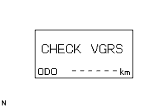
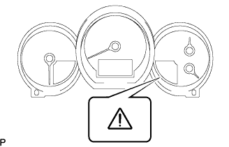
If a malfunction occurs during system operation, the master warning light (VGRS) on the combination meter assembly will come on and "CHECK VGRS" will be displayed on the multi-information display to inform the driver of the system malfunction.
 |
| DTCs |
Normal mode.
DTCs are memorized in the steering control ECU and read by using the intelligent tester (Click here).
Test mode.
By switching from normal mode to test mode, the steering angle sensor can be inspected (Click here).
- HINT:
- Whether the system is in diagnostic mode or test mode can be checked from the indication on the multi-information display. For details of the indication and how to check, refer to "DTC CHECK/CLEAR" (Click here).
 |
| CHECK MASTER WARNING LIGHT |
Turn the engine switch on (IG).
Check that the master warning light (VGRS) comes on for 2 seconds.
- HINT:
- If the master warning light (VGRS) check result is not normal, proceed to troubleshooting of the warning light circuit.
Trouble Area See procedure Master warning light circuit Click here
 |