Dtc B2610 Tilt Position Sensor Or Tilt Motor Circuit Malfunction
Steering. Lexus Gs430, Gs300. Uzs190 Grs190
DESCRIPTION
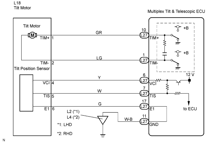
WIRING DIAGRAM
INSPECTION PROCEDURE
PERFORM ACTIVE TEST BY INTELLIGENT TESTER
CHECK HARNESS AND CONNECTOR (MULTIPLEX TILT & TELESCOPIC ECU - TILT MOTOR)
INSPECT TILT MOTOR
CHECK HARNESS AND CONNECTOR (MULTIPLEX TILT & TELESCOPIC ECU - TILT POSITION SENSOR)
CHECK HARNESS AND CONNECTOR (MULTIPLEX TILT & TELESCOPIC ECU - BODY GROUND)
INSPECT MULTIPLEX TILT & TELESCOPIC ECU (VCI, TIS TERMINAL VOLTAGE)
INSPECT TILT POSITION SENSOR
DTC B2610 Tilt Position Sensor or Tilt Motor Circuit Malfunction |
DESCRIPTION
The tilt motor is operated by the power source voltage supplied from the multiplex tilt & telescopic ECU and makes the steering column tilt up and down. The tilt position sensor (hole IC) in the tilt motor detects the tilt angle of the steering column and outputs a signal to the CPU based on that tilt.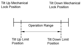
- HINT:
- Limit positions can be confirmed on the screen of the intelligent tester.
DTC No.
| Detection Item
| Trouble Area
|
B2610
| Tilt operation stops within the operation range while operating.
| - Wire harness or connector
- Tilt position sensor or tilt motor
- Multiplex tilt & telescopic ECU
|
WIRING DIAGRAM
INSPECTION PROCEDURE
| 1.PERFORM ACTIVE TEST BY INTELLIGENT TESTER |
Connect the intelligent tester to the DLC3.
Turn the engine switch on (IG) and turn the intelligent tester on.
Select "Tilt & Telescopic".
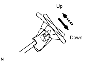
Select "Tilt", and perform the active test using the intelligent tester.
Check that the steering wheel tilts up (down) when the Active Test is carried out.
- OK:
- Steering wheel moves up (down).
| 2.CHECK HARNESS AND CONNECTOR (MULTIPLEX TILT & TELESCOPIC ECU - TILT MOTOR) |
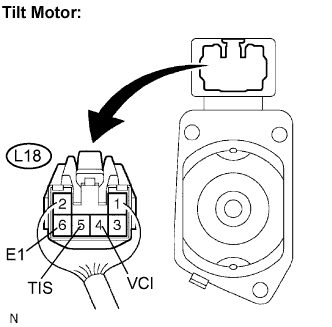
Disconnect the L27 connector from the multiplex tilt & telescopic ECU.
Disconnect the L18 connector from the tilt motor.
Measure the resistance according to the value(s) in the table below.
- Resistance:
Tester connection
(Terminal No.)
| Condition
| Specified value
|
TIM+ (L27-10) - TIM+ (L18-1)
| Always
| Below 1 Ω
|
TIM- (L27-1) - TIM- (L18-2)
| Always
| Below 1 Ω
|
TIM+ (L27-10) - Body ground
| Always
| 10 kΩ or higher
|
TIM- (L27-1) - Body ground
| Always
| 10 kΩ or higher
|
| | REPAIR OR REPLACE HARNESS OR CONNECTOR |
|
|
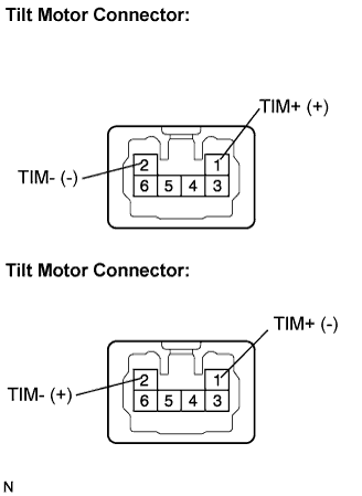
Connect the positive battery terminal to terminal TIM+ and the negative battery terminal to terminal TIM- of the tilt motor connector. Then confirm that the steering wheel tilts up.
- OK:
- Steering wheel moves up.
Connect the negative battery terminal to terminal TIM+ and the positive battery terminal to terminal TIM- of the tilt motor connector. Then confirm that the steering wheel tilts down.
- OK:
- Steering wheel moves down.
- NOTICE:
- 3UZ-FE:
- If replacing the steering column assembly, perform VGRS actuator angle initialization and VGRS actuator angle neutral calibration after wheel alignment adjustment (Click here for INITIALIZATION, Click here for CALIBRATION).
| | REPLACE STEERING COLUMN ASSEMBLY |
|
|
| OK |
|
|
|
| REPLACE MULTIPLEX TILT & TELESCOPIC ECU |
|
| 4.CHECK HARNESS AND CONNECTOR (MULTIPLEX TILT & TELESCOPIC ECU - TILT POSITION SENSOR) |
Disconnect the L27 connector from the multiplex tilt & telescopic ECU.
Disconnect the L18 connector from the tilt motor.
Measure the resistance according to the value(s) in the table below.
- Resistance:
Tester connection
(Terminal No.)
| Condition
| Specified value
|
VCI (L27-6) - VCI (L18-4)
| Always
| Below 1 Ω
|
TIS (L27-7) - TIS (L18-5)
| Always
| Below 1 Ω
|
E1 (L27-17) - E1 (L18-6)
| Always
| Below 1 Ω
|
VCI (L27-6) - Body ground
| Always
| 10 kΩ or higher
|
TIS (L27-7) - Body ground
| Always
| 10 kΩ or higher
|
E1 (L27-17) - Body ground
| Always
| 10 kΩ or higher
|
| | REPAIR OR REPLACE HARNESS OR CONNECTOR |
|
|
| 5.CHECK HARNESS AND CONNECTOR (MULTIPLEX TILT & TELESCOPIC ECU - BODY GROUND) |
Measure the resistance according to the value(s) in the table below.
- Resistance:
Tester connection
(Terminal No.)
| Condition
| Specified value
|
GND (L27-11) - Body ground
| Always
| Below 1 Ω
|
| | REPAIR OR REPLACE HARNESS OR CONNECTOR |
|
|
| 6.INSPECT MULTIPLEX TILT & TELESCOPIC ECU (VCI, TIS TERMINAL VOLTAGE) |
Reconnect the L27 connector to the multiplex tilt & telescopic ECU.
Measure the voltage according to the value(s) in the table below.
- Voltage:
Tester connection
(Terminal No.)
| Condition
| Specified value
|
VCI (L18-4) - E1 (L18-6)
| Engine switch on (IG)
| 8 to 16 V
|
TIS (L18-5) - E1 (L18-6)
| Engine switch on (IG)
| 8 to 16 V
|
| | REPLACE MULTIPLEX TILT & TELESCOPIC ECU |
|
|
| 7.INSPECT TILT POSITION SENSOR |
Reconnect the L18 connector to the tilt motor.
Measure the voltage according to the value(s) in the table below.
- Voltage:
Tester connection
(Terminal No.)
| Condition
| Specified value
|
TIS (L27-7) - E1 (L27-17)
| Steering tilts up or tilts down
| 8 to 16 V (Pulse HI)
|
0 V (Pulse LOW)
|
- NOTICE:
- 3UZ-FE:
- If replacing the steering column assembly, perform VGRS actuator angle initialization and VGRS actuator angle neutral calibration after wheel alignment adjustment (Click here for INITIALIZATION, Click here for CALIBRATION).
| | REPLACE STEERING COLUMN ASSEMBLY |
|
|
| OK |
|
|
|
| REPLACE MULTIPLEX TILT & TELESCOPIC ECU |
|