Tire Pressure Warning System Ecu Power Source Circuit
DESCRIPTION
WIRING DIAGRAM
INSPECTION PROCEDURE
INSPECT BATTERY
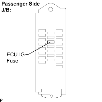
INSPECT FUSE (ECU-IG)
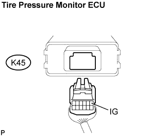
INSPECT TIRE PRESSURE MONITOR ECU
CHECK HARNESS AND CONNECTOR (BATTERY - TIRE PRESSURE MONITOR ECU)
CHECK HARNESS AND CONNECTOR (TIRE PRESSURE MONITOR ECU - BODY GROUND)
TIRE PRESSURE WARNING SYSTEM - ECU Power Source Circuit |
DESCRIPTION
This is the power source for the tire pressure monitor ECU. It also supplies the power to the tire pressure monitor receiver via the ECU.
WIRING DIAGRAM
INSPECTION PROCEDURE
Check the battery voltage.
- Standard voltage:
- 11 to 14 V
Remove the ECU-IG fuse from the passenger side J/B.
Check continuity of the ECU-IG fuse.
- Standard:
- Continuity exists.
| | CHECK FOR SHORT IN ALL HARNESSES AND CONNECTORS CONNECTED TO FUSE AND REPLACE FUSE |
|
|
| 3.INSPECT TIRE PRESSURE MONITOR ECU |
Remove the tire pressure monitor ECU with connectors being connected.
Turn the engine switch on (IG).
Measure the voltage according to the value(s) in the table below.
- Standard voltage:
Tester Connection
| Specified Condition
|
K45-1 (IG) - K45-4 (GND2)
| 10 to 14 V
|
| OK |
|
|
|
| REPLACE TIRE PRESSURE MONITOR ECU |
|
| 4.CHECK HARNESS AND CONNECTOR (BATTERY - TIRE PRESSURE MONITOR ECU) |
Disconnect the tire pressure monitor ECU K45 connector.
Turn the engine switch on (IG).
Measure the voltage according to the value(s) in the table below.
- Standard voltage:
Tester Connection
| Specified Condition
|
K45-1 (IG) - Body ground
| 10 to 14 V
|
| | REPAIR OR REPLACE HARNESS OR CONNECTOR |
|
|
| 5.CHECK HARNESS AND CONNECTOR (TIRE PRESSURE MONITOR ECU - BODY GROUND) |
Disconnect the tire pressure monitor ECU K45 connector.
Measure the resistance according to the value(s) in the table below.
- Standard resistance:
Tester Connection
| Specified Condition
|
K45-4 (GND2) - Body ground
| Below 1 Ω
|
| | REPAIR OR REPLACE HARNESS OR CONNECTOR |
|
|
| OK |
|
|
|
| REPLACE TIRE PRESSURE MONITOR ECU |
|