Tire Pressure Warning System Tire Pressure Warning Reset Switch Circuit
DESCRIPTION
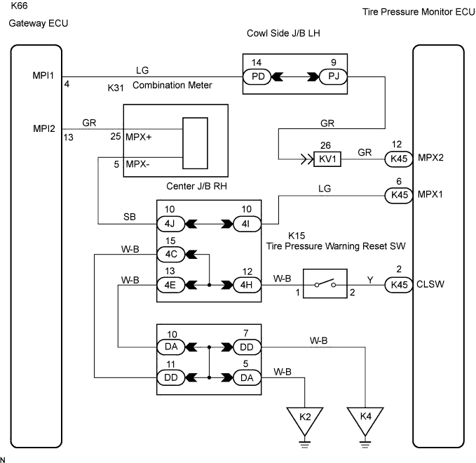
WIRING DIAGRAM
INSPECTION PROCEDURE
CHECK TIRE PRESSURE WARNING RESET SWITCH FUNCTION
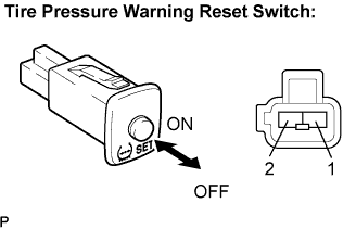
INSPECT TIRE PRESSURE WARNING RESET SWITCH
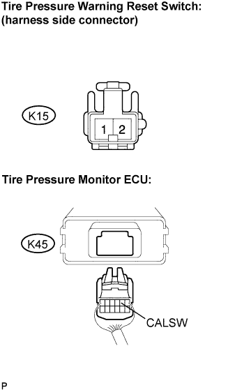
CHECK HARNESS AND CONNECTOR (TIRE PRESSURE WARNING RESET SWITCH-TIRE PRESSURE MONITOR ECU)
TIRE PRESSURE WARNING SYSTEM - Tire Pressure Warning Reset Switch Circuit |
DESCRIPTION
Receiving the signal from the tire pressure warning reset switch, the tire pressure monitor ECU indicates the initialization of the pressure warning system.
WIRING DIAGRAM
INSPECTION PROCEDURE
- NOTICE:
- It is necessary to register an ID code after replacing the tire pressure monitor valve sub-assembly and/or the tire pressure monitor ECU (Click here).
| 1.CHECK TIRE PRESSURE WARNING RESET SWITCH FUNCTION |
Perform the tire pressure warning reset switch test in TEST MODE PROCEDURE (Click here).
- OK:
- Reset switch ON:
- Tire pressure warning light comes on.
- Reset switch OFF:
- Tire pressure warning light blinks.
| 2.INSPECT TIRE PRESSURE WARNING RESET SWITCH |
Disconnect the tire pressure warning reset switch connector.
Measure the resistance between terminals 1 and 2 of the tire pressure warning reset switch when the tire pressure warning switch is ON and OFF.
- OK:
Switch Condition
| Specified Condition
|
ON
| Below 1 Ω
|
OFF
| 10 kΩ or higher
|
| | REPLACE TIRE PRESSURE WARNING RESET SWITCH |
|
|
| 3.CHECK HARNESS AND CONNECTOR (TIRE PRESSURE WARNING RESET SWITCH-TIRE PRESSURE MONITOR ECU) |
Disconnect the tire pressure warning reset switch K15 connector and tire pressure monitor ECU K45 connector.
Measure the resistance according to the value(s) in the table below.
- OK:
Tester Connection
| Specified Condition
|
K45-2 (CALSW) - K15-1
| Below 1 Ω
|
K45-2 (CALSW) - Body ground
| 10 kΩ or higher
|
| | REPAIR OR REPLACE HARNESS OR CONNECTOR |
|
|
| OK |
|
|
|
| REPLACE TIRE PRESSURE MONITOR ECU |
|