Front Acceleration Sensor Replacement
DISCONNECT CABLE FROM NEGATIVE BATTERY TERMINAL
REMOVE FRONT DOOR SCUFF PLATE LH
REMOVE FRONT DOOR OPENING TRIM COVER LH
REMOVE INSTRUMENT SIDE PANEL LH (for RHD)
REMOVE INSTRUMENT PANEL UNDER COVER SUB-ASSEMBLY NO.1 (for LHD)
REMOVE INSTRUMENT PANEL UNDER COVER SUB-ASSEMBLY NO.2 (for RHD)
REMOVE INSTRUMENT PANEL AIRBAG ASSEMBLY LOWER NO.2 (for RHD)
REMOVE GLOVE COMPARTMENT DOOR ASSEMBLY (for RHD)
REMOVE ACCELERATION SENSOR ASSEMBLY (for LHD)
REMOVE ACCELERATION SENSOR ASSEMBLY (for RHD)
REMOVE ACCELERATION SENSOR (for LHD)
REMOVE ACCELERATION SENSOR (for RHD)
INSTALL ACCELERATION SENSOR (for LHD)
INSTALL ACCELERATION SENSOR (for RHD)
INSTALL ACCELERATION SENSOR ASSEMBLY (for LHD)
INSTALL ACCELERATION SENSOR ASSEMBLY (for RHD)
INSTALL GLOVE COMPARTMENT DOOR ASSEMBLY (for RHD)
INSTALL INSTRUMENT PANEL AIRBAG ASSEMBLY LOWER NO.2 (for RHD)
INSTALL INSTRUMENT PANEL UNDER COVER SUB-ASSEMBLY NO.1 (for LHD)
INSTALL INSTRUMENT PANEL UNDER COVER SUB-ASSEMBLY NO.2 (for RHD)
INSTALL INSTRUMENT SIDE PANEL LH (for RHD)
INSTALL FRONT DOOR OPENING TRIM COVER LH
INSTALL FRONT DOOR SCUFF PLATE LH
CONNECT CABLE TO NEGATIVE BATTERY TERMINAL
INSPECT SRS WARNING LIGHT (for RHD)
INSPECT ADAPTIVE VARIABLE SUSPENSION SYSTEM
PERFORM INITIALIZATION
Front Acceleration Sensor -- Replacement |
| 1. DISCONNECT CABLE FROM NEGATIVE BATTERY TERMINAL |
(Click here)
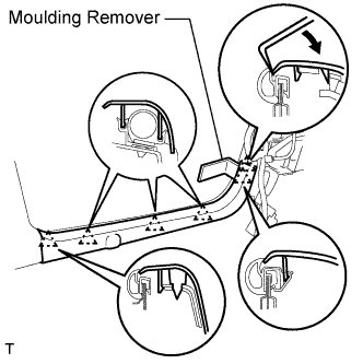
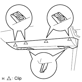
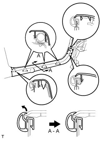
| 2. REMOVE FRONT DOOR SCUFF PLATE LH |
Using a moulding remover, detach the 5 claws and remove the scuff plate.
| 3. REMOVE FRONT DOOR OPENING TRIM COVER LH |
Using a moulding remover, detach the 3 claws and remove the trim cover.
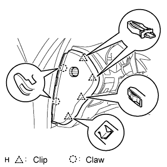
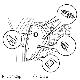
| 4. REMOVE INSTRUMENT SIDE PANEL LH (for RHD) |
Using a screwdriver, detach the 2 claws and 4 clips, and remove the side panel.
- HINT:
- Tape the screwdriver tip before use.
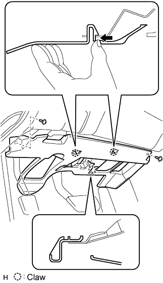
| 5. REMOVE INSTRUMENT PANEL UNDER COVER SUB-ASSEMBLY NO.1 (for LHD) |
Remove the 2 screws.
Detach the 2 claws.
Remove the under cover and then disconnect the connector.
| 6. REMOVE INSTRUMENT PANEL UNDER COVER SUB-ASSEMBLY NO.2 (for RHD) |
Using a screwdriver, detach the 4 clips.
- HINT:
- Tape the screwdriver tip before use.
Disconnect the connector and clamp, and remove the under cover.
| 7. REMOVE INSTRUMENT PANEL AIRBAG ASSEMBLY LOWER NO.2 (for RHD) |
Remove the 3 bolts and front passenger side knee airbag assembly.
Disconnect the connector.
- NOTICE:
- When handling the airbag connector, take care not to damage the airbag wire harness.
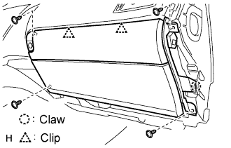
| 8. REMOVE GLOVE COMPARTMENT DOOR ASSEMBLY (for RHD) |
Remove the 4 screws.
Detach the 2 clips and claw.
Disconnect the connector and clamp.
Remove the glove compartment door.
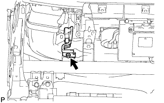
| 9. REMOVE ACCELERATION SENSOR ASSEMBLY (for LHD) |
Disconnect the acceleration sensor connector.
Remove the nut and the acceleration sensor assembly.
| 10. REMOVE ACCELERATION SENSOR ASSEMBLY (for RHD) |
Disconnect the acceleration sensor connector.
Remove the nut and the acceleration sensor assembly.
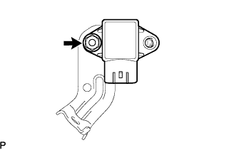
| 11. REMOVE ACCELERATION SENSOR (for LHD) |
Remove the nut and the acceleration sensor from the bracket.
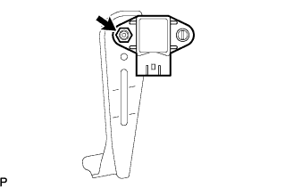
| 12. REMOVE ACCELERATION SENSOR (for RHD) |
Remove the nut and the acceleration sensor from the bracket.
| 13. INSTALL ACCELERATION SENSOR (for LHD) |
Install the acceleration sensor to the bracket with the nut.
- Torque:
- 7.8 N*m{80 kgf*cm, 69 in.*lbf}
- NOTICE:
- Do not drop the acceleration sensor. If it is dropped, replace it with a new one.
| 14. INSTALL ACCELERATION SENSOR (for RHD) |
Install the acceleration sensor to the bracket with the nut.
- Torque:
- 7.8 N*m{80 kgf*cm, 69 in.*lbf}
- NOTICE:
- Do not drop the acceleration sensor. If it is dropped, replace it with a new one.
| 15. INSTALL ACCELERATION SENSOR ASSEMBLY (for LHD) |
Install the acceleration sensor assembly with the nut.
- Torque:
- 8.5 N*m{87 kgf*cm, 75 in.*lbf}
- NOTICE:
- Do not drop the acceleration sensor. If it is dropped, replace it with a new one.
| 16. INSTALL ACCELERATION SENSOR ASSEMBLY (for RHD) |
Install the acceleration sensor assembly with the nut.
- Torque:
- 8.5 N*m{87 kgf*cm, 75 in.*lbf}
- NOTICE:
- Do not drop the acceleration sensor. If it is dropped, replace it with a new one.
| 17. INSTALL GLOVE COMPARTMENT DOOR ASSEMBLY (for RHD) |
Attach the 2 clips and claw to install the glove compartment door.
Connect the connector and clamp.
Install the 4 screws.
| 18. INSTALL INSTRUMENT PANEL AIRBAG ASSEMBLY LOWER NO.2 (for RHD) |
Connect the connector.
- NOTICE:
- When handling the airbag connector, take care not to damage the airbag wire harness.
Install the front passenger side knee airbag assembly with the 3 bolts.
- Torque:
- 10 N*m{102 kgf*cm, 7 ft.*lbf}
| 19. INSTALL INSTRUMENT PANEL UNDER COVER SUB-ASSEMBLY NO.1 (for LHD) |
Connect the connectors.
Attach the 2 claws to install the under cover.
Install the 2 screws.
| 20. INSTALL INSTRUMENT PANEL UNDER COVER SUB-ASSEMBLY NO.2 (for RHD) |
Connect the connector and clamp.
Attach the 4 clips to install the under cover.
| 21. INSTALL INSTRUMENT SIDE PANEL LH (for RHD) |
Attach the 2 claws and 4 clips to install the side panel.
| 22. INSTALL FRONT DOOR OPENING TRIM COVER LH |
| 23. INSTALL FRONT DOOR SCUFF PLATE LH |
Attach the 5 claws to install the scuff plate.
Pull out the folded lip of the weatherstrip.
| 24. CONNECT CABLE TO NEGATIVE BATTERY TERMINAL |
| 25. INSPECT SRS WARNING LIGHT (for RHD) |
(Click here)
| 26. INSPECT ADAPTIVE VARIABLE SUSPENSION SYSTEM |
(Click here)
| 27. PERFORM INITIALIZATION |
Some systems need initialization when disconnecting the cable from the negative battery terminal (Click here).