Dtc C1725 Front Damping Force Control Actuator Rh Circuit
DESCRIPTION
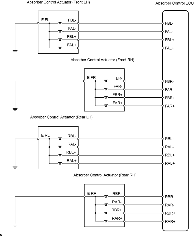
WIRING DIAGRAM
INSPECTION PROCEDURE
INSPECT ABSORBER CONTROL ACTUATOR OPERATION
RECONFIRM DTC
CHECK HARNESS AND CONNECTOR (ABSORBER CONTROL ACTUATOR CIRCUIT)
INSPECT ABSORBER CONTROL ACTUATOR (EACH ABSORBER CONTROL ACTUATOR)
RECONFIRM DTC
DTC C1725 Front Damping Force Control Actuator RH Circuit |
DTC C1726 Front Damping Force Control Actuator LH Circuit |
DTC C1727 Rear Damping Force Control Actuator RH Circuit |
DTC C1728 Rear Damping Force Control Actuator LH Circuit |
DESCRIPTION
The absorber control actuator changes the damping forces of the absorbers according to the signal output from the absorber control ECU.DTC No.
| DTC Detection Condition
| Trouble Area
|
C1725
| - When either of the following is detected:
- An actuator open-circuit signal is detected for at least 1 second when the actuator operates.
- An actuator short-circuit signal is consecutively detected 8 times when the actuator operates.
| - Right front absorber control actuator
- Right front absorber control actuator circuit
- Absorber control ECU
|
C1726
| - When either of the following is detected:
- An actuator open-circuit signal is detected for at least 1 second when the actuator operates.
- An actuator short-circuit signal is consecutively detected 8 times when the actuator operates.
| - Left front absorber control actuator
- Left front absorber control actuator circuit
- Absorber control ECU
|
C1727
| - When either of the following is detected:
- An actuator open-circuit signal is detected for at least 1 second when the actuator operates.
- An actuator short-circuit signal is consecutively detected 8 times when the actuator operates.
| - Right rear absorber control actuator
- Right rear absorber control actuator circuit
- Absorber control ECU
|
C1728
| - When either of the following is detected:
- An actuator open-circuit signal is detected for at least 1 second when the actuator operates.
- An actuator short-circuit signal is consecutively detected 8 times when the actuator operates.
| - Left rear absorber control actuator
- Left rear absorber control actuator circuit
- Absorber control ECU
|
WIRING DIAGRAM
INSPECTION PROCEDURE
- NOTICE:
- When replacing the absorber control ECU, check the acceleration sensor assembly signal after replacement (Click here).
- HINT:
- Check the condition of each related circuit connector before troubleshooting (Click here).
- When C1774 is output, inspect and repair the trouble areas indicated by C1774 first (Click here).
| 1.INSPECT ABSORBER CONTROL ACTUATOR OPERATION |
Connect the intelligent tester to DLC3.
Turn the engine switch on (IG) and turn the intelligent tester main switch on.
Select "Active Test" mode on the intelligent tester (Click here).
Active Test: EMSItem
| Vehicle Condition / Test Details
| Diagnostic Note
|
Damper Step FR
| Changes damper step / min.: 1 step, max.: 17 step
| Shock absorber hardens as damper step increases
|
Damper Step FL
| Changes damper step / min.: 1 step, max.: 17 step
| Shock absorber hardens as damper step increases
|
Damper Step RR
| Changes damper step / min.: 1 step, max.: 17 step
| Shock absorber hardens as damper step increases
|
Damper Step RL
| Changes damper step / min.: 1 step, max.: 17 step
| Shock absorber hardens as damper step increases
|
Check if the absorber control actuator operates to harden the suspension with the intelligent tester.
- OK:
- The absorber control actuator operates.
- HINT:
- The operation of the absorber control actuator can be checked at OPERATION CHECK (Click here).
- OK:
- The absorber control actuator operates normally.
Clear the DTC (Click here).
Perform a road test.
Check that the same DTC is recorded (Click here).
- Result:
Result
| Proceed To
|
DTC is output
| A
|
DTC is output (When troubleshooting accordance with the PROBLEM SYMPTOMS TABLE)
| B
|
DTC is not output
| C
|
| | PROCEED TO NEXT CIRCUIT INSPECTION SHOWN IN PROBLEM SYMPTOMS TABLE |
|
|
| |
|
| A |
|
|
|
| REPLACE ABSORBER CONTROL ECU |
|
| 3.CHECK HARNESS AND CONNECTOR (ABSORBER CONTROL ACTUATOR CIRCUIT) |
Disconnect the absorber control ECU connector and absorber control actuator connector.
Measure the resistance according to the value(s) in the table below.
- Resistance:
- C1725 (Front LH):
Tester Connection
| Specified Condition
|
A39-5 (FAL+) - A12-2 (A+)
| Below 1 Ω
|
A39-14 (FAL-) - A12-5 (A-)
| Below 1 Ω
|
A39-6 (FBL+) - A12-1 (B+)
| Below 1 Ω
|
A39-16 (FBL-) - A12-4 (B-)
| Below 1 Ω
|
A39-5 (FAL+) - Body ground
| 10 kΩ or higher
|
A39-6 (FBL+) - Body ground
| 10 kΩ or higher
|
A39-14 (FAL-) - Body ground
| 10 kΩ or higher
|
A39-16 (FBL-) - Body ground
| 10 kΩ or higher
|
A12-3 (E) - Body ground
| Below 1 Ω
|
- Resistance:
- C1726 (Front RH):
Tester Connection
| Specified Condition
|
A39-1 (FAR+) - A27-2 (A+)
| Below 1 Ω
|
A39-2 (FAR-) - A27-5 (A-)
| Below 1 Ω
|
A39-3 (FBR+) - A27-1 (B+)
| Below 1 Ω
|
A39-4 (FBR-) - A27-4 (B-)
| Below 1 Ω
|
A39-1 (FAR+) - Body ground
| 10 kΩ or higher
|
A39-2 (FAR-) - Body ground
| 10 kΩ or higher
|
A39-3 (FBR+) - Body ground
| 10 kΩ or higher
|
A39-4 (FBR-) - Body ground
| 10 kΩ or higher
|
A27-3 (E) - Body ground
| Below 1 Ω
|
- Resistance:
- C1727 (Rear LH):
Tester Connection
| Specified Condition
|
V2-6 (RAL+) - W27-2 (A+)
| Below 1 Ω
|
V2-7 (RAL-) - W27-5 (A-)
| Below 1 Ω
|
V2-8 (RBL+) - W27-1 (B+)
| Below 1 Ω
|
V2-9 (RBL-) - W27-4 (B-)
| Below 1 Ω
|
V2-6 (RAL+) - Body ground
| 10 kΩ or higher
|
V2-7 (RAL-) - Body ground
| 10 kΩ or higher
|
V2-8 (RBL+) - Body ground
| 10 kΩ or higher
|
V2-9 (RBL-) - Body ground
| 10 kΩ or higher
|
W27-3 (E) - Body ground
| Below 1 Ω
|
- Resistance:
- C1728 (Rear RH):
Tester Connection
| Specified Condition
|
V2-2 (RAR+) - V24-2 (A+)
| Below 1 Ω
|
V2-3 (RAR-) - V24-5 (A-)
| Below 1 Ω
|
V2-4 (RBR+) - V24-1 (B+)
| Below 1 Ω
|
V2-5 (RBR-) - V24-4 (B-)
| Below 1 Ω
|
V2-2 (RAR+) - Body ground
| 10 kΩ or higher
|
V2-3 (RAR-) - Body ground
| 10 kΩ or higher
|
V2-4 (RBR+) - Body ground
| 10 kΩ or higher
|
V2-5 (RBR-) - Body ground
| 10 kΩ or higher
|
V24-3 (E) - Body ground
| Below 1 Ω
|
| | REPAIR OR REPLACE HARNESS OR CONNECTOR (ABSORBER CONTROL ACTUATOR TO ABSORBER CONTROL ECU) |
|
|
| 4.INSPECT ABSORBER CONTROL ACTUATOR (EACH ABSORBER CONTROL ACTUATOR) |
SHAFT STOP POSITION CHECK
Remove the absorber control actuator (Click here for front, Click here for rear).
Connect the connector to the absorber control actuator.
Check absorber control actuator operation (Click here).
- Shift to the Test Mode and start the engine.
- Check the shaft rotation when depressing the brake pedal.
- OK:
- The shaft rotates by 15°.
- HINT:
- The shaft rotates from the hard to soft position by 15° up to a maximum angle of 120° every time the brake pedal is depressed.
ACTUATOR CHECK
Disconnect the absorber control actuator connector.
Measure the resistance according to the value(s) in the table below.
- Resistance:
Tester Connection
| Specified Condition
|
1 (B+) - 3 (GND)
| 12.0 to 12.8 Ω
|
2 (A+) - 3 (GND)
| 12.0 to 12.8 Ω
|
4 (B-) - 3 (GND)
| 12.0 to 12.8 Ω
|
5 (A-) - 3 (GND)
| 12.0 to 12.8 Ω
|
| | REPLACE ABSORBER CONTROL ACTUATOR |
|
|
Clear the DTC (Click here).
Perform a road test.
Check that the same DTC is recorded (Click here).
- HINT:
- Reinstall the sensor connector, etc. and restore the vehicle to its prior condition before rechecking for DTCs.
- Result:
Result
| Proceed To
|
DTC is output
| A
|
DTC is output (When troubleshooting accordance with the PROBLEM SYMPTOMS TABLE)
| B
|
DTC is not output
| C
|
| | PROCEED TO NEXT CIRCUIT INSPECTION SHOWN IN PROBLEM SYMPTOMS TABLE |
|
|
| |
|
| A |
|
|
|
| REPLACE ABSORBER CONTROL ECU |
|