Dtc C1787 Ems Switch Circuit (Test Mode Dtc)
DESCRIPTION
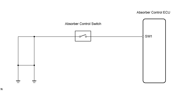
WIRING DIAGRAM
INSPECTION PROCEDURE
READ VALUE OF INTELLIGENT TESTER
RECONFIRM DTC
INSPECT ABSORBER CONTROL SWITCH
CHECK HARNESS AND CONNECTOR (ABSORBER CONTROL SWITCH TO ABSORBER CONTROL ECU, BODY GROUND)
RECONFIRM DTC
DTC C1787 EMS Switch Circuit (Test Mode DTC) |
DESCRIPTION
- The absorber control switch (EMS Switch) is a switch which selects the damping force mode of shock absorber.
- The absorber control ECU reads the changes in each signal when performing the Test Mode check and outputs the DTC (C1787) if there is no change.
DTC No.
| DTC Detection Condition
| Trouble Area
|
C1787
| There is no change in the absorber control switch signal when performing the Test Mode check.
| - Absorber control switch
- Absorber control switch circuit
- Absorber control ECU
|
WIRING DIAGRAM
INSPECTION PROCEDURE
- NOTICE:
- When replacing the absorber control ECU, check the acceleration sensor assembly signal after replacement (Click here).
- HINT:
- Check the condition of each related circuit connector before troubleshooting (Click here).
- When C1774 is output, inspect and repair the trouble areas indicated by C1774 first (Click here).
| 1.READ VALUE OF INTELLIGENT TESTER |
Connect the intelligent tester to DLC3.
Turn the engine switch on (IG) and turn the intelligent tester main switch on.
Select "Data List" mode on the intelligent tester (Click here).
Data List: EMSItem
| Measurement Item/
Range (Display)
| Normal Condition
| Diagnostic Note
|
Damping Force Switch 1
| Damper force switch 1 (absorber control switch) /
ON or OFF
| The same as absorber control switch position
| Operate the absorber control switch
|
Operate the absorber control switch and check its operation in the Data List on the intelligent tester display.
- OK:
- The display on the intelligent tester changes according to the operation of the absorber control switch.
Clear the DTC (Click here).
Perform the Test Mode (Click here).
Check if the same DTC is recorded (Click here).
- Result:
Result
| Proceed To
|
DTC is output
| A
|
DTC is output (When troubleshooting accordance with the PROBLEM SYMPTOMS TABLE)
| B
|
DTC is not output
| C
|
| | PROCEED TO NEXT CIRCUIT INSPECTION SHOWN IN PROBLEM SYMPTOMS TABLE |
|
|
| |
|
| A |
|
|
|
| REPLACE ABSORBER CONTROL ECU |
|
| 3.INSPECT ABSORBER CONTROL SWITCH |
Remove the absorber control switch.
Disconnect the absorber control switch connector.
Measure the resistance according to the value(s) in the table below.
- Resistance:
Tester Connection
| Switch Position
| Specified Condition
|
Switch terminal 4 -
Switch terminal 3
| NORM
| 10 kΩ or higher
(No Continuity)
|
Switch terminal 4 -
Switch terminal 3
| SPORT
| Below 1 Ω
(Continuity)
|
| | REPLACE ABSORBER CONTROL SWITCH |
|
|
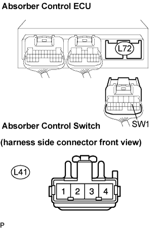
| 4.CHECK HARNESS AND CONNECTOR (ABSORBER CONTROL SWITCH TO ABSORBER CONTROL ECU, BODY GROUND) |
Disconnect the absorber control ECU connector.
Measure the resistance according to the value(s) in the table below.
- Resistance:
Tester Connection
| Specified Condition
|
L72-9 (SW1) - L41-4
| Below 1 Ω
|
L72-9 (SW1) - Body ground
| 10 kΩ or higher
|
Measure the resistance according to the value(s) in the table below.
- Resistance:
Tester Connection
| Specified Condition
|
L41-3 - Body ground
| Below 1 Ω
|
| | REPAIR OR REPLACE HARNESS OR CONNECTOR |
|
|
Clear the DTC (Click here).
Perform Test Mode (Click here).
Check if the same DTC is recorded (Click here).
- HINT:
- Reinstall the sensor, connectors, etc. and restore the vehicle to its prior condition before rechecking for DTCs.
- Result:
Result
| Proceed To
|
DTC is output
| A
|
DTC is output (When troubleshooting accordance with the PROBLEM SYMPTOMS TABLE)
| B
|
DTC is not output
| C
|
| | PROCEED TO NEXT CIRCUIT INSPECTION SHOWN IN PROBLEM SYMPTOMS TABLE |
|
|
| |
|
| A |
|
|
|
| REPLACE ABSORBER CONTROL ECU |
|