Dtc C1715 Front Acceleration Sensor Rh
DESCRIPTION
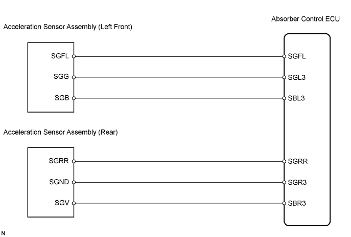
WIRING DIAGRAM
INSPECTION PROCEDURE
READ VALUE OF INTELLIGENT TESTER
RECONFIRM DTC
INSPECT ACCELERATION SENSOR ASSEMBLY (LEFT FRONT)
INSPECT ACCELERATION SENSOR ASSEMBLY (REAR)
CHECK HARNESS AND CONNECTOR (ABSORBER CONTROL ECU TO ACCELERATION SENSOR ASSEMBLY)
RECONFIRM DTC
DTC C1715 Front Acceleration Sensor RH |
DTC C1716 Front Acceleration Sensor LH |
DTC C1717 Rear Acceleration Sensor |
DTC C1791 Front Acceleration Sensor RH (Test Mode DTC) |
DTC C1792 Front Acceleration Sensor LH (Test Mode DTC) |
DTC C1793 Rear Acceleration Sensor (Test Mode DTC) |
DESCRIPTION
The acceleration sensor assembly detects the amount of vertical force applied to the vehicle when accelerating or decelerating (G (up and down)). The acceleration sensor assemblies are mounted at 3 spots, which are in the absorber control ECU and at the front and rear of the cabin, to independently detect the amount of vertical force applied to the vehicle. The acceleration sensor assembly converts the resistance, which changes according to the acceleration level, into an electric signal, and output it to the absorber control ECU.The absorber control ECU detects the changes in each signal when performing the Test Mode check and outputs the Test Mode DTCs (C1791, C1792, C1793) if there is no change.DTC No.
| DTC Detection Condition
| Trouble Area
|
C1715
C1791
| - When either of the following continues for 0.5 seconds or more:
- A signal of -9.8m/s2 to 9.8m/s2 or less is not input from the acceleration sensor assemblies to the absorber control ECU with the engine switch on (IG).
- The power source voltage of the right front acceleration sensor assembly is 5.5 V or higher or 4.3 V or lower.
| Absorber control ECU
(Houses right front acceleration sensor)
|
C1716
C1792
| - When either of the following continues for 0.5 seconds or more:
- A signal of -9.8m/s2 to 9.8m/s2 or less is not input from the acceleration sensor assemblies to the absorber control ECU with the engine switch on (IG).
- The power source voltage of the left front acceleration sensor assembly is 5.5 V or higher or 4.3 V or lower.
| - Left front acceleration sensor assembly
- Left front acceleration sensor assembly circuit
- Absorber control ECU
|
C1717
C1793
| - When either of the following continues for 0.5 seconds or more:
- A signal of -9.8m/s2 to 9.8m/s2 or less is not input from the acceleration sensor assemblies to the absorber control ECU with the engine switch on (IG).
- The power source voltage of the rear acceleration sensor assembly is 5.5 V or higher or 4.3 V or lower.
| - Rear acceleration sensor assembly
- Rear acceleration sensor assembly circuit
- Absorber control ECU
|
- HINT:
- DTC Nos. C1715 and C1791 are the right front acceleration sensor assembly.
- DTC Nos. C1716 and C1792 are the left front acceleration sensor assembly.
- DTC Nos. C1717 and C1793 are the rear acceleration sensor assembly.
- Since the right front acceleration sensor assembly is built into the absorber control ECU, replace the absorber control ECU when DTCs C1715 and C1791 are output.
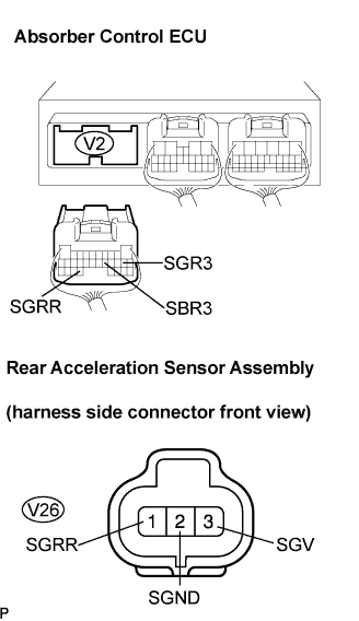
WIRING DIAGRAM
INSPECTION PROCEDURE
- NOTICE:
- When replacing the absorber control ECU, check the acceleration sensor assembly signal after replacement (Click here).
- HINT:
- Check the condition of each related circuit connector before troubleshooting (Click here).
- When C1774 is output, inspect and repair the trouble areas indicated by C1774 first (Click here).
| 1.READ VALUE OF INTELLIGENT TESTER |
Connect the intelligent tester to DLC3.
Turn the engine switch on (IG) and turn the intelligent tester main switch on.
Select "Data List" mode on the intelligent tester (Click here).
Data List: EMSItem
| Measurement Item/
Range (Display)
| Normal Condition
| Diagnostic Note
|
G (Up & Down) Sensor FR
| G (up & down) FR sensor reading / min.: -1045267.3 mm/s 2, max.: 1045299.2 mm/s2
| -8820 mm/s2 to 980 mm/s2 at still condition
| Reading changes when the vehicle (FR) is bounced
|
G (Up & Down) Sensor FL
| G (up & down) FL sensor reading / min.: -1045267.3 mm/s 2, max.: 1045299.2 mm/s2
| -8820 mm/s2 to 980 mm/s2 at still condition
| Reading changes when the vehicle (FL) is bounced
|
G (Up & Down) Sensor Rear
| G (up & down) rear sensor reading / min.: -1045267.3 mm/s 2, max.: 1045299.2 mm/s2
| -8820 mm/s2 to 980 mm/s2 at still condition
| Reading changes when the vehicle (rear) is bounced
|
Check that the value of the acceleration sensor read on the intelligent tester changes as the vehicle is bounced.
- OK:
- Acceleration value must change.
- Result:
Result
| Proceed To
|
OK
| A
|
NG (Front right)
| A
|
NG (Front left)
| B
|
NG (Rear)
| C
|
Clear the DTC (Click here).
Perform a road test.
Check if the same DTC is detected (Click here).
- Result:
Result
| Proceed To
|
DTC is output
| A
|
DTC is output (When troubleshooting accordance with the PROBLEM SYMPTOMS TABLE)
| B
|
DTC is not output
| C
|
| | PROCEED TO NEXT CIRCUIT INSPECTION SHOWN IN PROBLEM SYMPTOMS TABLE |
|
|
| |
|
| A |
|
|
|
| REPLACE ABSORBER CONTROL ECU |
|
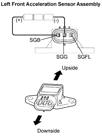
| 3.INSPECT ACCELERATION SENSOR ASSEMBLY (LEFT FRONT) |
Remove the left front acceleration sensor assembly (Click here).
Connect 3 1.5 V dry batteries in series.
Connect terminal 3 (SGB) to the front battery's positive (+) terminal, and terminal 2 (SGG) to the rear battery's negative (-) terminal.
Measure the voltage according to the value(s) in the table below.
- Voltage:
Tester connection
| Sensor condition
| Voltage
|
SGFL (1) - SGG (2)
| Sensor stationary
| Approx. 2.3 V
|
SGFL (1) - SGG (2)
| Sensor vibrating vertically
| Change between approx.
1.0 to 4.0 V
|
- NOTICE:
- Do not apply a voltage of more than 6 V.
- Do not drop the acceleration sensor assembly. If it is dropped, replace it with a new one.
- The acceleration sensor assembly removed from the vehicle must not be placed upside down.
- HINT:
- When the acceleration sensor assembly is tilted, it may output a different value.
| | REPLACE ACCELERATION SENSOR ASSEMBLY |
|
|
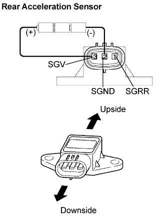
| 4.INSPECT ACCELERATION SENSOR ASSEMBLY (REAR) |
Remove the rear acceleration sensor assembly (Click here).
Connect the 3 1.5 V dry batteries in series.
Connect terminal 3 (SGV) to the front battery's positive (+) terminal, and terminal 2 (SGND) to the rear battery's negative (-) terminal.
Measure the voltage according to the value(s) in the table below.
- Voltage:
Tester connection
| Sensor condition
| Voltage
|
SGRR (1) - SGND (2)
| Sensor stationary
| Approx. 2.3 V
|
SGRR (1) - SGND (2)
| Sensor vibrating vertically
| Change between approx.
1.0 to 4.0 V
|
- NOTICE:
- Do not apply a voltage of more than 6 V.
- Do not drop the acceleration sensor assembly. If it is dropped, replace it with a new one.
- The acceleration sensor assembly removed from the vehicle must not be placed upside down.
- HINT:
- When the acceleration sensor is tilted, it may output the different value.
| | REPLACE ACCELERATION SENSOR ASSEMBLY |
|
|
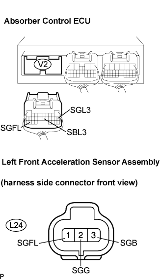
| 5.CHECK HARNESS AND CONNECTOR (ABSORBER CONTROL ECU TO ACCELERATION SENSOR ASSEMBLY) |
Front: (C1716, C1792)
Disconnect the absorber control ECU connector and acceleration sensor assembly connector.
Measure the resistance according to the value(s) in the table below.
- Resistance:
Tester connection
| Specified condition
|
V2-29 (SGFL) - L24-1 (SGFL)
| Below 1 Ω
|
V2-11 (SGL3) - L24-2 (SGG)
| Below 1 Ω
|
V2-16 (SBL3) - L24-3 (SGB)
| Below 1 Ω
|
V2-29 (SGFL) - Body ground
| 10 kΩ or higher
|
V2-11 (SGL3) - Body ground
| 10 kΩ or higher
|
V2-16 (SBL3) - Body ground
| 10 kΩ or higher
|
REAR: (C1717, C1793)
Measure the resistance according to the value(s) in the table below.
- Resistance:
Tester connection
| Specified condition
|
V2-27 (SGRR) - V26-1 (SGRR)
| Below 1 Ω
|
V2-12 (SGR3) - V26-2 (SGND)
| Below 1 Ω
|
V2-15 (SBR3) - V26-3 (SGV)
| Below 1 Ω
|
V2-27 (SGRR) - Body ground
| 10 kΩ or higher
|
V2-12 (SGR3) - Body ground
| 10 kΩ or higher
|
V2-15 (SBR3) - Body ground
| 10 kΩ or higher
|
| | REPAIR OR REPLACE HARNESS OR CONNECTOR |
|
|
Clear the DTC (Click here).
Perform a road test.
Check if the same DTC is detected (Click here).
- HINT:
- Reinstall the sensor, connectors, etc. and restore the vehicle to its prior condition before rechecking for DTCs.
- Result:
Result
| Proceed To
|
DTC is output
| A
|
DTC is output (When troubleshooting in accordance with the PROBLEM SYMPTOMS TABLE)
| B
|
DTC is not output
| C
|
| | PROCEED TO NEXT CIRCUIT INSPECTION SHOWN IN PROBLEM SYMPTOMS TABLE |
|
|
| |
|
| A |
|
|
|
| REPLACE ABSORBER CONTROL ECU |
|