Transmission. Lexus Gs430, Gs300. Uzs190 Grs190
A960E Automatic Transmission. Lexus Gs430, Gs300. Uzs190 Grs190
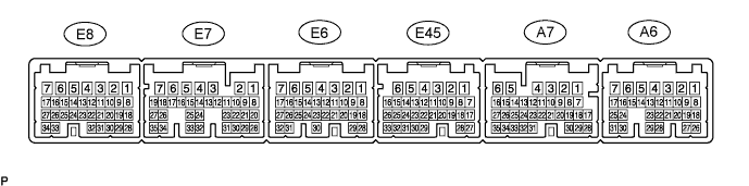
Electronic Controlled Automatic Transmission System -- Terminals Of Ecm |
| ECM |
- HINT:
- Each ECM terminal's standard voltage is shown in the table below.
- In the table, first follow the information under "Condition". Look under "Symbols (Terminal No.)" for the terminals to inspected. The standard voltage between the terminals is shown under "Specific Condition".
- Use the illustration above as a reference for the ECM terminals.
| Symbols (Terminals No.) | Wiring Color | Terminal Description | Condition | Specified Condition |
| D (E7-9) - E1 (E7-7) | R-W - BR | D shift position switch signal | Engine switch on (IG) and shift lever D and S position | 10 to 14 V |
| ↑ | ↑ | ↑ | Engine switch on (IG) and shift lever except D and S position | Below 1 V |
| R (E7-8) - E1 (E7-7) | R - BR | R shift position switch signal | Engine switch on (IG) and shift lever R position | 10 to 14 V |
| ↑ | ↑ | ↑ | Engine switch on (IG) and shift lever except R position | Below 1 V |
| STP (A7-4) - E1 (E7-7) | G - BR | Stop light switch signal | Brake pedal is depressed | 7.5 to 14 V |
| ↑ | ↑ | ↑ | Brake pedal is released | Below 1.5 V |
| SFTD (A7-19) - E1 (E7-7) | O - BR | Down shift switch signal | Engine switch on (IG) and shift lever S position | 10 to 14 V |
| ↑ | ↑ | ↑ | Engine switch on (IG) and shift lever "-" position (Down shift) | Below 1 V |
| SFTU (A7-30) - E1 (E7-7) | Y-R - BR | Up shift switch signal | Engine switch on (IG) and shift lever S position | 10 to 14 V |
| ↑ | ↑ | ↑ | Engine switch on (IG) and shift lever "+" position (Up shift) | Below 1 V |
| S (A7-9) - E1 (E7-7) | W-G - BR | S shift position switch signal | Engine switch on (IG) and shift lever S position | 10 to 14 V |
| ↑ | ↑ | ↑ | Engine switch on (IG) and shift lever except S position | Below 1 V |
| P (E7-6) - E1 (E7-7) | W - BR | Park position switch signal | Engine switch on (IG) and shift lever P position | 10 to 14 V |
| ↑ | ↑ | ↑ | Engine switch on (IG) and shift lever except P position | Below 1 V |
| N (E7-32) - E1 (E7-7) | G-R - BR | Neutral position switch signal | Engine switch on (IG) and shift lever N position | 10 to 14 V |
| ↑ | ↑ | ↑ | Engine switch on (IG) and shift lever except N position | Below 1 V |
| STAR (E7-4) - E1 (E7-7) | L-Y - BR | Park neutral switch signal | Engine switch on (IG) and shift lever P and N position | Below 1 V |
| ↑ | ↑ | ↑ | Engine switch on (IG) and shift lever except P and N position | 10 to 14 V |
| SLU+ (E7-13) - SLU- (E7-12) | L-Y - L-R | SLU solenoid signal | 5th (lock-up) or 6th (lock-up) gear | Pulse generation (See waveform 2) |
| SR (E7-2) - E1 (E7-7) | G-W - BR | SR solenoid signal | 1st, 2nd, 3rd or 4th gear | 10 to 14 V |
| ↑ | ↑ | ↑ | 5th or 6th gear | Below 1 V |
| S4 (E7-16) - E1 (E7-7) | G-R - BR | S4 solenoid signal | 5th or 6th gear | 10 to 14 V |
| ↑ | ↑ | ↑ | 1st, 2nd, 3rd or 4th gear | Below 1 V |
| S3 (E7-17) - E1 (E7-7) | G - BR | S3 solenoid signal | 1st, 2nd or 3rd gear | 10 to 14 V |
| ↑ | ↑ | ↑ | 4th, 5th or 6th gear | Below 1 V |
| S2 (E7-18) - E1 (E7-7) | W - BR | S2 solenoid signal | 1st, 2nd or 6th gear | 10 to 14 V |
| ↑ | ↑ | ↑ | 3rd, 4th or 5th gear | Below 1 V |
| S1 (E7-19) - E1 (E7-7) | R - BR | S1 solenoid signal | 1st gear | Below 1 V |
| ↑ | ↑ | ↑ | Except 1st gear | 10 to 14 V |
| SL2+ (E7-11) - SL2- (E7-10) | L-W - W | SL2 solenoid signal | Engine idle speed | Pulse generation (See waveform 3) |
| SL1+ (E7-25) - SL1- (E7-24) | Y - L | SL1 solenoid signal | 5th or 6th gear | Pulse generation (See waveform 4) |
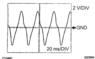
| SP2+ (E7-23) - SP2- (E7-22) | L - Y | Speed sensor (SP2) signal | Vehicle speed 20 km/h (12 mph) | Pulse generation (See waveform 6) |
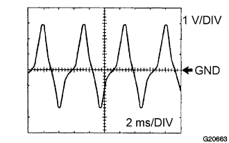
| NT+ (E7-21) - NT- (E7-20) | R - G | Speed sensor (NT) signal | Engine idle speed | Pulse generation (See waveform 5) |
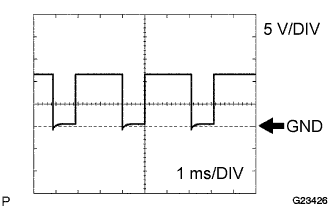
| SLT+ (E7-35) - SLT- (E7-34) | B - G-B | SLT solenoid signal | Engine idle speed | Pulse generation (See waveform 1) |
| OIL (E7-27) - EOIL (E7-26) | G-Y - BR | ATF temperature sensor signal | ATF temperature: 115°C (239°F) or more | Below 1.5 V |
| KD (A6-26) - E1 (E7-7) | O - BR | Kick-down switch signal | Engine switch on (IG) and Accelerator pedal is depressed | Below 1 V |
| ↑ | ↑ | ↑ | Engine switch on (IG) and Accelerator pedal is released | 10 to 14 V |
Waveform 1
Reference: Terminal SLT+ - SLT- Tool setting 5 V/DIV, 1ms/DIV Vehicle condition Engine idle speed Waveform 2
Reference: Terminal SLU+ - SLU- Tool setting 5 V/DIV, 1ms/DIV Vehicle condition 5th (lock-up) or 6th (lock-up) gear Waveform 3
Reference: Terminal SL2+ - SL2- Tool setting 5 V/DIV, 1ms/DIV Vehicle condition Engine idle speed Waveform 4
Reference: Terminal SL1+ - SL1- Tool setting 5 V/DIV, 1ms/DIV Vehicle condition 5th or 6th gear Waveform 5
Reference: Terminal NT+ - NT- Tool setting 1 V/DIV, 2ms/DIV Vehicle condition Engine idle speed (P or N position) Waveform 6
Reference: Terminal SP2+ - SP2- Tool setting 2 V/DIV, 20ms/DIV Vehicle condition Vehicle speed 20 km/h (12 mph)
 |
|
|
|
 |
 |
| Cowl Side J/B ECU (Multiplex network Body ECU) |
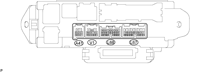
- HINT:
- Each ECU terminal's standard voltage is shown in the table below.
- In the table, first follow the information under "Condition". Look under "Symbols (Terminal No.)" for the terminals to inspected. The standard voltage between the terminals is shown under "Specific Condition".
- Use the illustration above as a reference for the ECU terminals.
| Symbols (Terminals No.) | Wiring Color | Terminal Description | Condition | Specified Condition |
| PWR (L68-18) - Body ground | P | PWR switch signal | Engine switch on (IG) and Pattern select switch (PWR) ON | 0 to 1.5 V |
| ↑ | ↑ | ↑ | Engine switch on (IG) and Pattern select switch (PWR) OFF | Pulse generation *1 |
| SNOW (L68-17) - Body ground | L | SNOW switch signal | Engine switch on (IG) and Pattern select switch (SNOW) ON | 0 to 1.5 V |
| ↑ | ↑ | ↑ | Engine switch on (IG) and Pattern select switch (SNOW) OFF | Pulse generation *1 |
- HINT:
- *1: Voltage is input intermittently as this is an intermittent circuit. (Voltage varies between a peak of 7.5 to 14 V and a low of 0 to1.5 V.)