Oil Pump -- Removal |
| 1. DISCHARGE FUEL SYSTEM PRESSURE |
- CAUTION:
- Do not disconnect any part of the fuel system until you have discharged the fuel system pressure.
- Even after discharging the fuel pressure, place a shop rag over fittings as you separate them to reduce the risk of fuel spray on yourself or in the engine compartment.
Disconnect the cable from the negative (-) battery terminal.
- NOTICE:
- Wait at least 90 seconds after disconnecting the cable from the negative (-) battery terminal to prevent airbag and seat belt pretensioner activation.
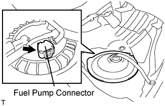
Disconnect the fuel pump connector.
 |
Connect the cable to the negative (-) battery terminal.
Start the engine. After the engine has stopped on its own, turn the engine switch off.
- HINT:
- DTC P0171/P0172 (system too lean) may be set.
Crank the engine again, then check that the engine does not start.
Loosen the fuel tank cap, then discharge the pressure in the fuel tank completely.
Connect the fuel pump connector.
| 2. DISCONNECT CABLE FROM NEGATIVE BATTERY TERMINAL |
- CAUTION:
- Wait at least 90 seconds after disconnecting the cable from the negative (-) battery terminal to prevent airbag and seat belt pretensioner activation.
| 3. DRAIN ENGINE OIL |
Remove the drain plug.
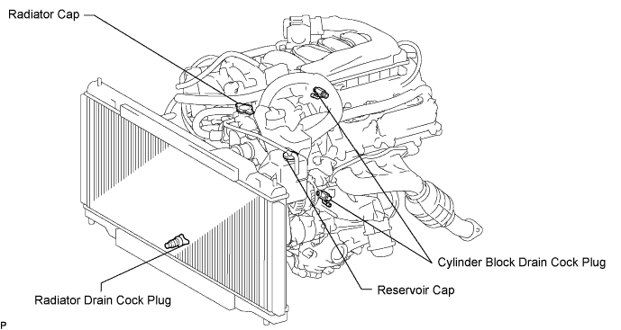
| 4. DRAIN ENGINE COOLANT |
- CAUTION:
- Do not remove the radiator cap while the engine and radiator are still hot. Pressurized, hot engine coolant and steam may be released and cause serious burns.
Remove the radiator cap and reservoir cap.
Loosen the radiator drain cock plug and 2 cylinder block drain cock plugs. Then drain the coolant.
- HINT:
- Collect the coolant in a container and dispose of it according to the regulations in your area.
| 5. DRAIN AUTOMATIC TRANSMISSION FLUID |
Add the automatic transmission fluid following the flow chart below.
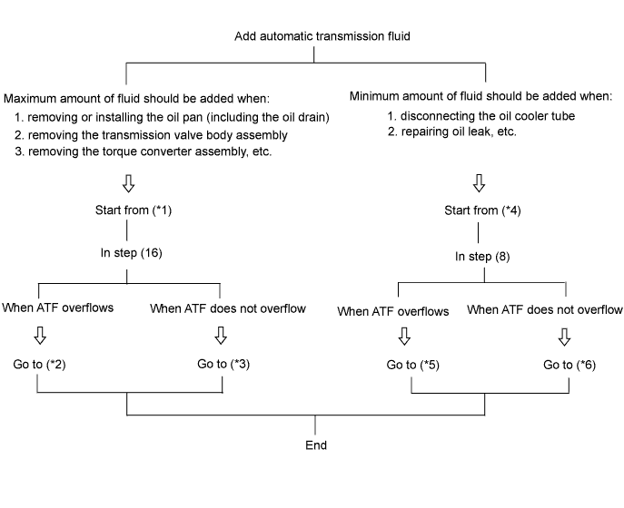
When adding the maximum amount of fluid: [*1]
Lift up the vehicle.
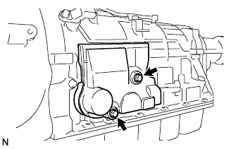
Remove the 2 bolts and transmission case cover.
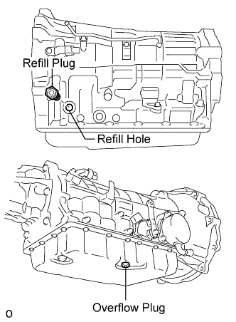
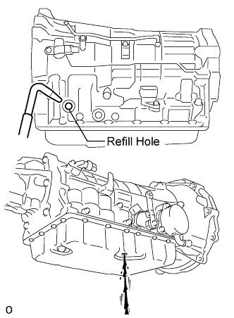
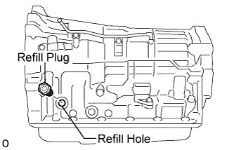
Remove the refill plug and overflow plug.
Add ATF through the refill hole until it drains out from the overflow hole.
- NOTICE:
- Be sure to use ATF WS.
Install a new gasket and the overflow plug.
- Torque:
- 20 N*m{204 kgf*cm, 15 ft.*lbf}
Add proper amount of ATF through the refill hole.
- NOTICE:
- Refill amount differs depending on the related procedures indicated below.
Related procedures Refill amount Removal and installation of oil pan
(Including the oil drain)1.1 liters (1.2 US qts, 1.0 lmp.qts) Removal of transmission valve body assembly 2.5 liters (2.6 US qts, 2.2 lmp.qts) Removal of torque converter assembly 4.2 liters (4.4 US qts, 3.7 lmp.qts) Install a new O-ring and the refill plug.
- Torque:
- 39 N*m{400 kgf*cm, 53 ft.*lbf}
Lower the vehicle.
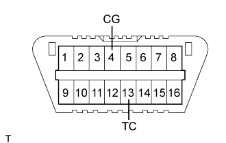
Using SST, create a short-circuit between terminals TC and CG of the DLC3.
- SST
- 09843-18040
Start the engine.
- NOTICE:
- Be sure to place the key inside the cabin in order to start the engine.
- Turn the A/C off.
Slowly move the shift lever from the P to the S position, shift the gear from 1st to 6th and then return the shift lever to the P position.
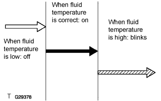
Switch to the fluid temperature detection mode.
- Move the shift lever from the N to the D position, or from D to N, within 1.5 seconds.
- Continue this procedure for 6 seconds or more.
- Standard:
- Meter indicator light "D" comes on for 2 seconds and then goes off.
- Move the shift lever from the N to the D position, or from D to N, within 1.5 seconds.
Return the shift lever to the P position and disconnect terminal TC after confirming the above condition.
Idle the engine to raise fluid temperature.
Lift up the vehicle immediately after meter indicator light "D" comes on.
- NOTICE:
- Add fluid only when the meter indicator light is on.
- Perform this procedure while the engine is idling.
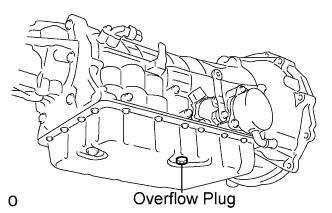
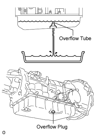
Remove the overflow plug. If ATF overflows, proceed to [*2].
If ATF does not overflow, proceed to [*3].- HINT:
- "Overflow" indicates the condition under which ATF drains out from the overflow tube.
When fluid overflows: [*2]
- NOTICE:
- Capacity of the overflow tube is approximately 3 cc.
Install a new gasket and the overflow plug when the draining ATF has become a trickle.
- Torque:
- 20 N*m{204 kgf*cm, 15 ft.*lbf}
- NOTICE:
- Be careful when handling the drained ATF as it will be hot.
Install a new O-ring and tighten the refill plug.
- Torque:
- 39 N*m{400 kgf*cm, 29 ft.*lbf}
Install the transmission case cover with the 2 bolts.
- Torque:
- 5.4 N*m{55 kgf*cm, 48 in.*lbf}
Lower the vehicle.
Turn the engine switch off and remove the SST.
 |
When fluid does not overflow:[*3]
Remove the refill plug.
Add ATF through the refill hole until it drains out from the overflow hole.
Install a new gasket and the overflow plug when the draining ATF has become a trickle.
- Torque:
- 20 N*m{204 kgf*cm, 15 ft.*lbf}
Install a new O-ring and tighten the refill plug.
- Torque:
- 39 N*m{400 kgf*cm, 29 ft.*lbf}
Install the transmission case cover with the 2 bolts.
- Torque:
- 5.4 N*m{55 kgf*cm, 48 in.*lbf}
Lower the vehicle.
Turn the engine switch off and remove the SST.
|
When adding a minimum amount of fluid: [*4]
Using SST, create a short-circuit between terminals TC and CG of the DLC3.
- SST
- 09843-18040
Start the engine.
- NOTICE:
- Be sure to place the key inside the cabin in order to start the engine.
- Turn the A/C off.
Slowly move the shift lever from the P to the S position, shift the gear from 1st to 6th and then return the shift lever to the P position.
Switch to the fluid temperature detection mode.
- Move the shift lever from the N to the D position, or from D to N, within 1.5 seconds.
- Continue this procedure for 6 seconds or more.
- Standard:
- Meter indicator light "D" comes on for 2 seconds and then goes off.
- Move the shift lever from the N to the D position, or from D to N, within 1.5 seconds.
Return the shift lever to the P position and disconnect terminal TC after confirming the above condition.
Idle the engine to raise fluid temperature.
Lift up the vehicle immediately after meter indicator light "D" comes on.
- NOTICE:
- Add fluid only when the meter indicator light is on.
- Perform the procedure while the engine is idling.
Remove the overflow plug. If ATF overflows, proceed to [*5]. If ATF does not overflow, proceed to [*6].
- HINT:
- "Overflow" indicates the condition under which ATF drains out from the overflow tube.
|
When fluid overflows: [*5]
Install a new gasket and the overflow plug when the draining ATF has become a trickle.
- Torque:
- 20 N*m{204 kgf*cm, 15 ft.*lbf}
- NOTICE:
- Be careful when handling the drained ATF as it will be hot.
Install the transmission case cover with the 2 bolts.
- Torque:
- 5.4 N*m{55 kgf*cm, 48 in.*lbf}
Lower the vehicle.
Turn the engine switch off and remove the SST.
|
When fluid does not overflow: [*6]
Remove the refill plug.
Add ATF through the refill hole until it drains out from the overflow hole.
Install a new gasket and the overflow plug when the draining ATF has become a trickle.
- Torque:
- 20 N*m{204 kgf*cm, 15 ft.*lbf}
Install a new O-ring and tighten the refill plug.
- Torque:
- 39 N*m{400 kgf*cm, 29 ft.*lbf}
Install the transmission case cover with the 2 bolts.
- Torque:
- 5.4 N*m{55 kgf*cm, 48 in.*lbf}
Lower the vehicle.
Turn the engine switch off and remove the SST.
|
| 6. REMOVE ENGINE AND TRANSMISSION ASSEMBLY |
Remove the engine and transmission assembly (Click here).
| 7. REMOVE ENGINE WIRE |
Remove the engine wire.
| 8. REMOVE OIL DIPSTICK SUB-ASSEMBLY |
 |
Remove the oil level gauge.
Remove the 2 bolts, then remove the No. 1 and No. 2 oil dipstick guide.
Remove the O-ring from the oil dipstick guide.
| 9. REMOVE EXHAUST MANIFOLD SUB-ASSEMBLY RH |
Disconnect the heated oxygen sensor connector.
Remove the 6 nuts, exhaust manifold and gasket.
| 10. REMOVE EXHAUST MANIFOLD SUB-ASSEMBLY LH |
Disconnect the heated oxygen sensor connector.
Remove the 6 nuts, exhaust manifold and gasket.
| 11. REMOVE AUTOMATIC TRANSMISSION ASSEMBLY |
Remove the 9 bolts and automatic transmission assembly.
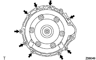 |
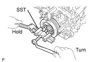
| 12. REMOVE DRIVE PLATE AND RING GEAR SUB-ASSEMBLY |
 |
Using SST, hold the crankshaft.
- SST
- 09213-70011(09213-70020)
09330-00021
Remove the 8 bolts, front spacer, drive plate and rear spacer.
 |
| 13. REMOVE FRONT ENGINE MOUNTING INSULATOR |
 |
Remove the 2 bolts, then remove the front suspension crossmember sub-assembly from the engine.
| 14. FIX ENGINE ONTO ENGINE STAND |
Fix the engine onto a engine stand with the bolts.
| 15. REMOVE GENERATOR ASSEMBLY |
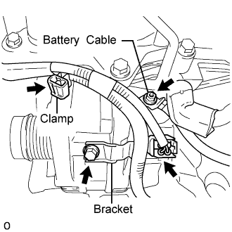 |
Detach the clamp, and remove the bolt from the generator.
Disconnect the generator connector.
Detach the rubber cap, and then remove the nut and battery cable.
Remove the nut, bolt and generator bracket.
 |
Remove the 2 bolts and generator.
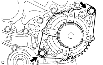 |
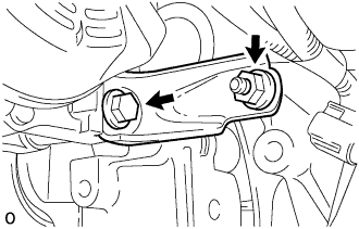
| 16. REMOVE NO. 2 IDLER PULLEY SUB-ASSEMBLY |
Remove the bolt, plate and idler pulley.
| 17. REMOVE V-RIBBED BELT TENSIONER ASSEMBLY |
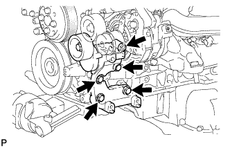 |
Remove the 5 bolts, then remove the V-ribbed belt tensioner assembly.
| 18. REMOVE WATER PUMP PULLEY |
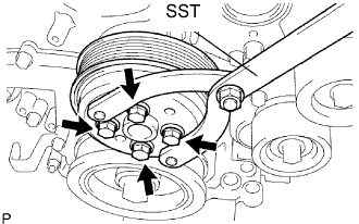 |
Using SST, hold the water pump pulley.
- SST
- 09960-10010(09962-01000,09963-00700)
Remove the 4 bolts and water pump pulley.
| 19. REMOVE INJECTOR DRIVER |
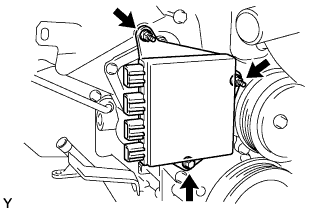 |
Remove the bolt, 2 nuts and injector driver.
- NOTICE:
- Be careful not to drop or strike the injector driver.
| 20. REMOVE WATER INLET ASSEMBLY |
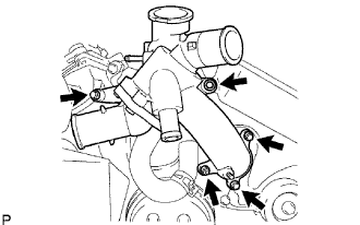 |
Remove the 3 water by-pass hoses.
Remove the 4 bolts, nut and water inlet.
Remove the O-rings.
| 21. REMOVE CRANKSHAFT PULLEY |
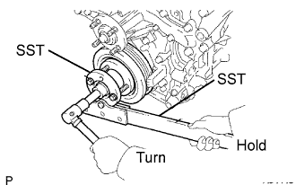 |
Using SST, loosen the crankshaft pulley bolt.
- SST
- 09213-70011(09213-70020)
09330-00021
Using SST, remove the crankshaft pulley bolt and crankshaft pulley.
- SST
- 09950-50013(09951-05010,09952-05010,09953-05020,09954-05021)
 |
| 22. REMOVE NO. 2 OIL PAN SUB-ASSEMBLY |
 |
Remove the 15 bolts and 2 nuts.
Insert the blade of SST between the oil pans. Cut through the applied sealer and remove the oil pan sub-assembly No. 2.
- SST
- 09032-00100
- NOTICE:
- Be careful not to damage the contact surfaces of the oil pans.
| 23. REMOVE OIL PAN SUB-ASSEMBLY |
 |
Remove the 16 bolts and 2 nuts.
- HINT:
- Be sure to clean the bolts and stud bolts and check the threads for cracks or other damage.
Remove the oil pan by prying between the oil pan and cylinder block with a screwdriver.
- NOTICE:
- Be careful not to damage the contact surfaces of the cylinder block and oil pan.
- HINT:
- Tape the screwdriver tip before use.
 |
Remove the 2 O-rings.
| 24. REMOVE OIL STRAINER SUB-ASSEMBLY |
 |
Remove the 3 nuts, oil strainer and gasket.
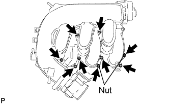
| 25. REMOVE INTAKE AIR SURGE TANK ASSEMBLY |
Remove the 2 bolts and intake manifold stay.
Remove the 4 bolts and 2 surge tank stays.
Using a 5 mm hexagon socket wrench, remove the 7 bolts, 2 nuts and gasket.
- HINT:
- Cover the intake manifold port to prevent foreign matter from entering it.
 |
| 26. REMOVE NO. 1 FUEL PIPE SUB-ASSEMBLY |
Disconnect the fuel pipe hose.
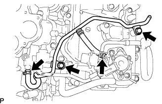 |
Remove the 2 bolts and fuel pipe.
| 27. REMOVE FUEL MAIN TUBE |
Remove the fuel pipe clamp.
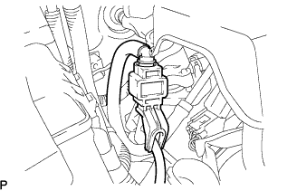 |
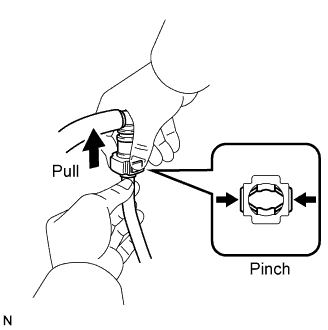
Pinch and pull the fuel tube's connector to disconnect it from the fuel main pipe.
- NOTICE:
- Check for foreign matter in the fuel tube around the fuel tube's connector. Clean it if necessary. Foreign matter can affect the O-ring's ability to seal the connector and fuel main pipe.
- Do not use any tools to separate the connector and pipe.
- Do not forcefully bend or twist the hose.
- Keep the connector and pipe free from foreign matter.
- If the connector and pipe are stuck together, pinch the connector and turn it carefully to disconnect it.
Put the connector in a plastic bag to prevent damage and contamination.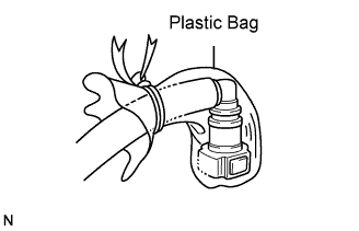
 |
| 28. REMOVE HIGH PRESSURE SIDE FUEL PUMP |
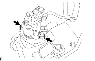 |
Disconnect the fuel hose.
Remove the 2 nuts, fuel pump and fuel pump insulator.
| 29. REMOVE NO. 2 FUEL PIPE SUB-ASSEMBLY |
Remove the fuel pipe from the fuel delivery pipe.
- NOTICE:
- Pull and remove the fuel pipe in a straight line to avoid damage to the seal surface of the delivery pipe's O-ring.
| 30. REMOVE IGNITION COIL ASSEMBLY |
Remove the 6 bolts and 6 ignition coils.
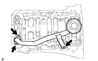
| 31. REMOVE NO. 1 OIL PIPE |
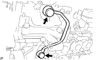 |
Remove the oil check valve bolt, oil pipe union and oil pipe.
Remove the oil control valve filter LH and gaskets.
| 32. REMOVE NO. 2 OIL PIPE |
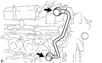 |
Remove the oil check valve bolt, oil pipe union and oil pipe.
Remove the oil control valve filter RH and gaskets.
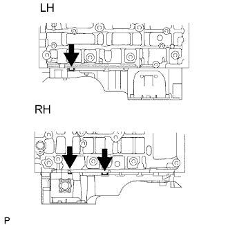
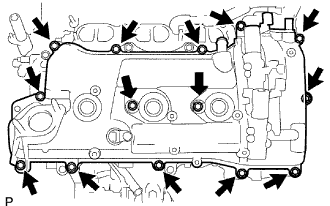
| 33. REMOVE CYLINDER HEAD COVER SUB-ASSEMBLY RH (for Bank 1) |
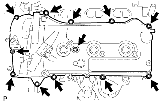 |
Remove the 12 bolts, head cover and gasket.
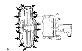
| 34. REMOVE CYLINDER HEAD COVER SUB-ASSEMBLY LH (for Bank 2) |
 |
Remove the 14 bolts, head cover and gasket.
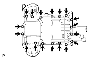
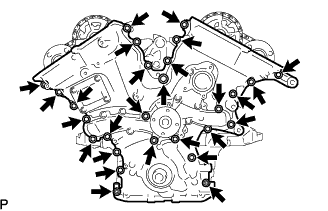
| 35. REMOVE TIMING CHAIN OR BELT COVER SUB-ASSEMBLY |
 |
Remove the bolt and wiring harness clamp bracket.
Remove the 25 bolts and 2 nuts shown in the illustration.
 |
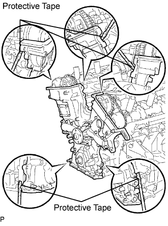
Remove the timing chain cover by prying between the timing chain cover and cylinder head or cylinder block with a screwdriver.
- NOTICE:
- Be careful not to damage the contact surfaces of the cylinder head, cylinder block and timing chain cover.
- HINT:
- Tape the screwdriver tip before use.
 |
Remove the gasket.
 |