Fuel Tank -- Installation |
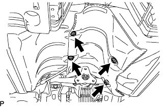
| 1. INSTALL NO. 1 FUEL TANK PROTECTOR SUB-ASSEMBLY |
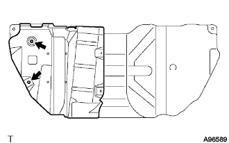 |
Install the tank protector with the 2 nuts.
- Torque:
- 5.0 N*m{51 kgf*cm, 44 in.*lbf}
| 2. INSTALL FUEL TANK CUSHION |
 |
Install the tank cushions and tank brackets.
| 3. INSTALL FUEL PUMP TUBE SUB-ASSEMBLY |
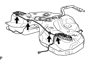 |
Install the fuel pump tube to the 4 clamps.
| 4. INSTALL FUEL TANK SUB-ASSEMBLY |
Set a mission jack to the fuel tank and lift it up.
Install the 2 fuel tank bands with the 4 bolts.
- Torque:
- 39 N*m{400 kgf*cm, 29 ft.*lbf}
Install the 2 nuts.
- Torque:
- 20 N*m{204 kgf*cm, 15 ft.*lbf}
| 5. CONNECT EMISSION HOSE |
 |
Connect the 2 emission hoses.
Install the bracket.
| 6. CONNECT FUEL TANK TO FILLER PIPE HOSE |
 |
Connect the fuel tank to filler pipe hose with the clamp.
| 7. CONNECT FUEL TANK MAIN TUBE SUB-ASSEMBLY |
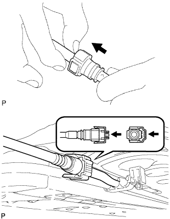 |
Connect the fuel tank main tube connector.
- HINT:
- Push the part together firmly until a "click" sound is heard.
- NOTICE:
- Before installing the tube connectors to the pipes, check if there is any damage or foreign matter in the connectors.
- After having finished the connection, check if the connectors and pipes are securely connected by trying to pull them apart.
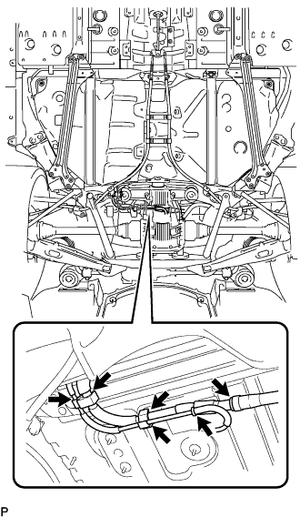
| 8. CONNECT PARKING BRAKE CABLE ASSEMBLY |
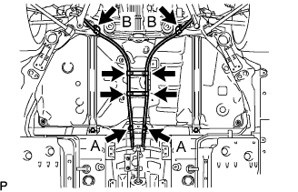 |
Connect the 4 clamps.
Connect the 2 parking brake cables with the 4 bolts.
- Torque:
- 6.0 N*m{61 kgf*cm, 53 in.*lbf}for bolt A
- 19 N*m{193 kgf*cm, 14 ft.*lbf}for bolt B
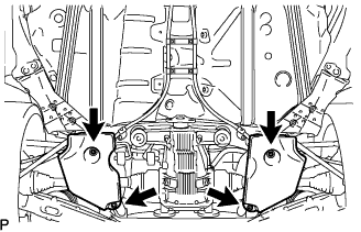
| 9. INSTALL REAR SUSPENSION MEMBER BRACE LH |
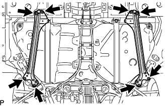 |
Install the suspension side member brace with the 4 bolts.
- Torque:
- 19 N*m{195 kgf*cm, 14 ft.*lbf}
| 10. INSTALL REAR SUSPENSION MEMBER BRACE RH |
Install the suspension member brace with the 4 bolts.
- Torque:
- 19 N*m{195 kgf*cm, 14 ft.*lbf}
| 11. INSTALL REAR FLOOR SIDE MEMBER COVER LH |
 |
Install the member cover with the 3 bolts.
| 12. INSTALL REAR FLOOR SIDE MEMBER COVER RH |
 |
Install the member cover with the 3 bolts.
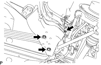
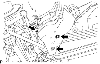
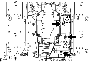
| 13. INSTALL NO. 1 DIFFERENTIAL SUPPORT PROTECTOR |
 |
Install the differential supporter with the 2 nuts.
| 14. INSTALL NO. 2 DIFFERENTIAL SUPPORT PROTECTOR |
Install the differential supporter with the 2 nuts.
| 15. INSTALL NO. 2 FUEL TANK PROTECTOR |
 |
Install the tank protector with the 4 nuts.
- Torque:
- 5.0 N*m{51 kgf*cm, 48 in.*lbf}
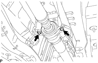
| 16. ADJUST PROPELLER WITH CENTER BEARING SHAFT ASSEMBLY |
Apply grease to the flexible coupling centering bushings.
- Grease:
- Molybdenum disulphide lithium base, NLGI No.2
 |
Install the propeller shaft from the vehicle's rear and connect the transmission and differential.
- NOTICE:
- Support the center support bearing by hand so that the transmission and intermediate shaft, and propeller shaft and differential, remain in a straight line.
Temporarily install the 2 center support bearing set bolts with the adjusting washers.
- HINT:
- Use the adjusting washers which were removed.
 |
Align the matchmarks on the transmission companion flange and flexible coupling.
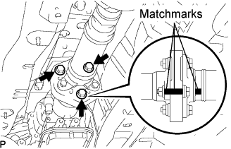 |
Temporarily install the 3 bolts, washers and nuts.
- HINT:
- The bolts should be installed from the propeller shaft side.
Align the matchmarks on the differential companion flange and flexible coupling.
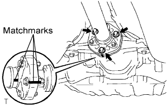 |
Temporarily install the 3 bolts, washers and nuts.
- HINT:
- The bolts should be installed from the propeller shaft side.
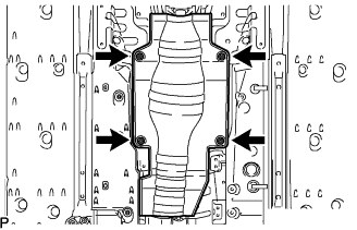
Tighten the 6 nuts.
- Torque:
- 79 N*m{805 kgf*cm, 58 ft.*lbf}
- NOTICE:
- Be careful not to damage the flexible coupling centering bushing.
| 17. INSTALL FRONT FLOOR NO. 1 HEAT INSULATOR |
 |
Install the heat insulator with the 4 nuts.
| 18. INSTALL FRONT FLOOR COVER CENTER LH |
 |
Install the floor cover center with the 3 nuts.
| 19. INSTALL EXHAUST PIPE ASSEMBLY |
Install the exhaust pipe (Click here).
| 20. INSTALL FUEL RETURN VENT TUBE SUB-ASSEMBLY |
Install the fuel sender gauge.
Set the fuel sender gauge to the fuel vent tube. Then slide the sender gauge downward to install it.
Connect the fuel sender gauge connector.
 |
Set the fuel return vent tube to the fuel tank.
 |
Apply a light coat of gasoline to a new gasket, and set it to the fuel tank.
Connect the fuel tube connector, and set the fuel suction with pump and gauge.
- NOTICE:
- Be careful not to bend the arm of the fuel sender gauge.
- When connecting the fuel tube connector, do not forcibly pull the tube.
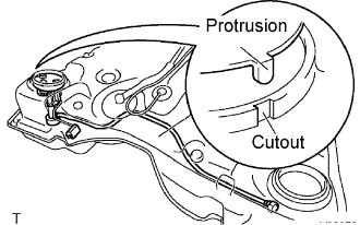
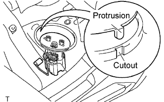
Align the protrusion of the fuel suction tube and the cutout of the fuel tank.
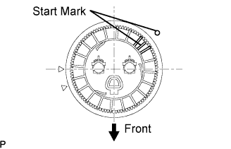
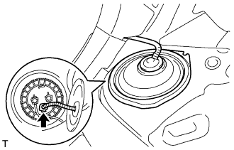
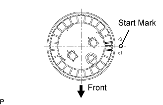
While holding the fuel suction tube by hand, align the start mark of a new fuel pump gauge retainer and the fuel tank. Install the fuel pump retainer to the fuel tank.
 |
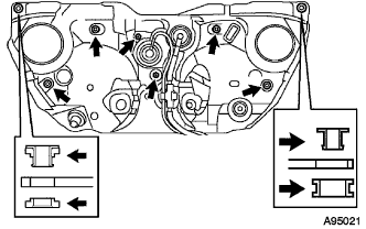
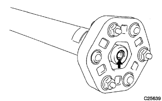
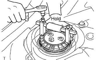
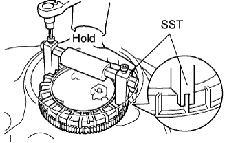
Using a 6 mm socket wrench, set SST to the fuel pump gauge retainer.
- SST
- 09808-14020
- NOTICE:
- Do not any other tools such as a screwdriver.
- HINT:
- Fit the tips of SST on the ribs of the retainer.
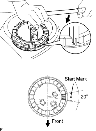
 |
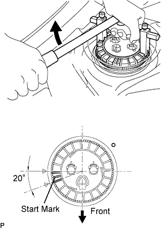
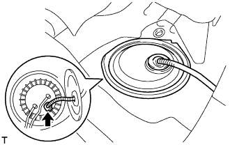
Hold SST with one hand and use SST to tighten the fuel pump gauge retainer 2 turns so that the starting mark on the retainer is within the indicated range in the illustration.
 |
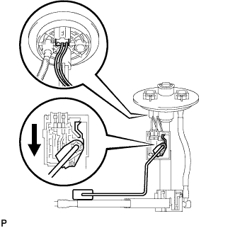
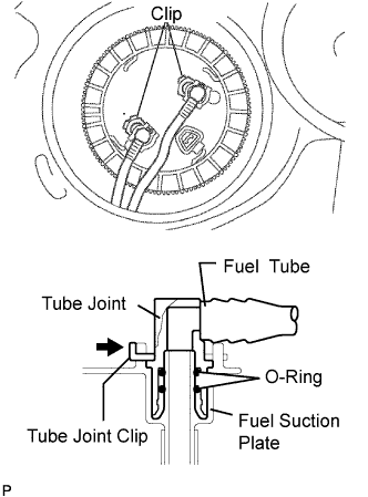
Connect the fuel pump tube.
Push the fuel tube joint into the plug of the fuel suction plate, then install the tube joint clip.
 |
Connect the fuel suction tube connector.
- NOTICE:
- Check that there are no scratches or foreign matter around the connected part of the fuel tube joint and plug before performing this work.
- Check that the fuel tube joint is securely inserted.
- Check that the tube joint clip is on the collar of the fuel tube joint.
- After installing the tube joint clip, check that the fuel tube cannot be pulled out.
| 21. INSTALL REAR FLOOR SERVICE HOLE COVER |
 |
Connect the fuel sender gauge connector.
Install the service hole cover with new butyl tape.
| 22. INSTALL FUEL SUCTION WITH PUMP AND GAUGE TUBE ASSEMBLY |
Apply a light coat of gasoline to a new gasket, and install it to the fuel tank.
Connect the fuel tube connector, and set the fuel suction with pump and gauge.
- NOTICE:
- Be careful not to bend the arm of the fuel sender gauge.
- When connecting the fuel tube connector, do not forcibly pull the tube.
Align the protrusion of the fuel suction tube and the cutout of the fuel tank.
 |
While holding the fuel suction tube by hand, align the starting marks of a new fuel pump gauge retainer and the fuel tank. Install the fuel pump retainer to the fuel tank.
 |
Using a 6 mm socket, set SST to the fuel pump gauge retainer.
- SST
- 09808-14020
- NOTICE:
- Do not any other tools such as a screwdriver.
- HINT:
- Fit the tips of SST on the ribs of the retainer.
 |
Hold SST with one hand and use SST to tighten the fuel pump gauge retainer 2 turns so that the starting mark on the retainer is within the indicated range in the illustration.
 |
Connect the fuel tank main tube and pump tube.
Push the fuel tube joint into the plug of the fuel suction plate, then install the 2 tube joint clips.
 |
Connect the fuel suction tube connector.
- NOTICE:
- Check that there are no scratches or foreign objects around the connected part of the fuel tube joint and plug before performing this work.
- Check that the fuel tube joint is securely inserted.
- Check that the tube joint clip is on the collar of the fuel tube joint.
- After installing the tube joint clip, check that the fuel tube cannot be pulled out.
| 23. INSTALL REAR FLOOR NO. 2 SERVICE HOLE COVER |
 |
Connect the fuel pump connector.
Install the service hole cover with new butyl tape.
| 24. INSTALL ROOM NO. 3 PARTITION PAD |
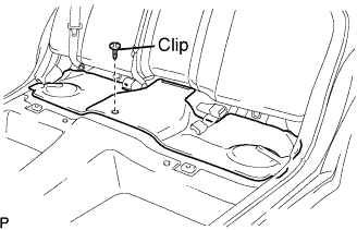 |
Install the partition pad with the clip.
| 25. INSTALL REAR SEAT CUSHION ASSEMBLY |
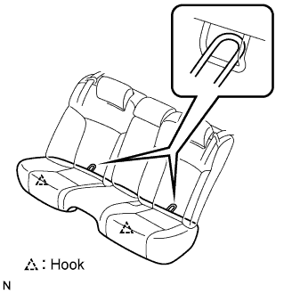 |
Attach the seat cushion's 2 rear hooks to the seatback.
Attach the seat cushion's 2 front hooks to the vehicle body.
Confirm that the seat cushion is firmly installed.
- NOTICE:
- When installing the seat cushion, make sure the seat belt buckle is not under the seat cushion.
| 26. CONNECT CABLE TO NEGATIVE BATTERY TERMINAL |
| 27. CHECK FOR FUEL LEAKS |
Start the engine, and check that there are no fuel leaks after performing maintenance anywhere on the system.
| 28. PERFORM INITIALIZATION |
Perform initialization (Click here).
- NOTICE:
- Certain systems need to be initialized after disconnecting and reconnecting the cable from the negative (-) battery terminal.