Engine Unit -- Inspection |
| 1. INSPECT CAMSHAFT |
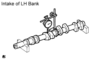
Inspect the circle runout.
Place the camshaft on V-blocks.
Using a dial indicator, measure the circle runout at the center journal.
- Maximum circle runout:
- 0.08 mm (0.0031 in.)
- If the circle runout is greater than the maximum, replace the camshaft.
 |
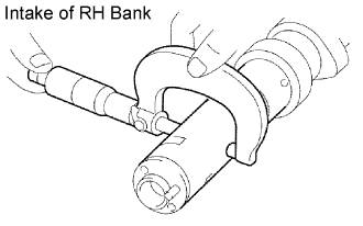
Using a micrometer, measure the cam lobe height.
- Standard cam lobe height:
- 42.610 to 42.710 mm (1.6776 to 1.6815 in.)
- Minimum cam lobe height:
- 42.46 mm (1.6717 in.)
- If the cam lobe height is less than the minimum, replace the camshaft.
 |
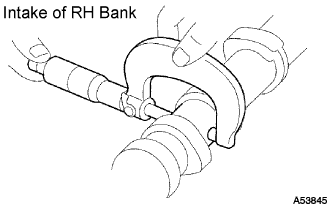
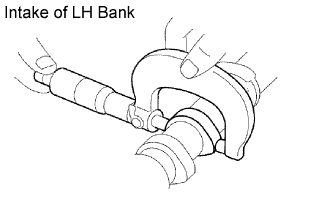
Inspect the journal diameter of the camshaft.
Using a micrometer, measure the journal diameter of the camshaft for the camshaft bearing.
- Journal diameter:
- 26.954 to 26.970 mm (1.0612 to 1.0618 in.)
- If the journal diameter is not as specified, check the oil clearance.
Using a micrometer, measure the journal diameter for the camshaft timing tube.
- Journal diameter:
- 30.984 to 31.000 mm (1.2198 to 1.2205 in.)
- If the journal diameter is not as specified, check the oil clearance.
 |
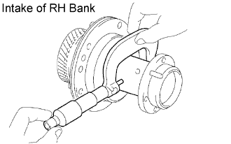
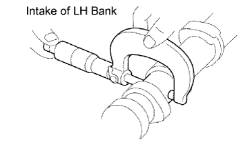
Inspect the journal diameter of the camshaft timing tube.
Using a micrometer, measure the journal diameter.
- Journal diameter:
- 39.955 to 39.964 mm (1.5730 to 1.5734 in.)
- If the journal diameter is not as specified, check the oil clearance.
 |
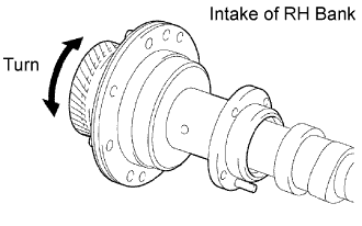
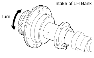
Install the camshaft timing tube to the camshaft, and check that the timing tube turns smoothly.
- If necessary, replace the timing tube and camshaft.
- If necessary, replace the timing tube and camshaft.
 |
Check the oil clearance.
Install the camshaft timing tube to the camshaft.
Clean the bearing caps and journals.
Check the bearings for flaking and scoring.
- If the bearings are damaged, replace the bearing caps and cylinder head as a set.
- If the bearings are damaged, replace the bearing caps and cylinder head as a set.
Place the camshaft on the cylinder head.
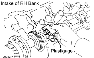
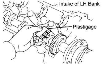
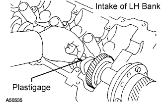
Lay a strip of Plastigage across each of the journals.
Install the bearing caps.
- NOTICE:
- Do not turn the camshaft.
Remove the bearing caps.
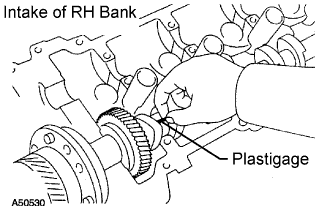
Measure the Plastigage at its widest point.
- Standard oil clearance:
Journal Oil clearance Camshaft journal 0.030 to 0.067 mm (0.0012 to 0.0026 in.) Camshaft timing tube journal 0.036 to 0.057 mm (0.0014 to 0.0022 in.)
- Maximum oil clearance:
Journal Oil clearance Camshaft journal 0.100 mm (0.0039 in.) Camshaft timing tube journal 0.075 mm (0.0030 in.)
- If the oil clearance is greater than the maximum, replace the camshaft and timing tube. If necessary, replace the bearing caps and cylinder head as a set.
Completely remove the Plastigage.
Remove the camshaft.
Remove the camshaft timing tube from the camshaft.
 |
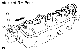
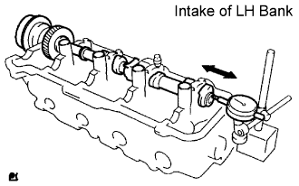
Check the thrust clearance.
Install the camshaft timing tube to the camshaft.
Install the camshaft.
Using a dial indicator, measure the thrust clearance while moving the camshaft back and forth.
- Standard thrust clearance:
- 0.060 to 0.100 mm (0.0024 to 0.0039 in.)
- Maximum thrust clearance:
- 0.13 mm (0.0051 in.)
- If the thrust clearance is greater than the maximum, replace the camshaft. If necessary, replace the bearing caps and cylinder head as a set.
Remove the camshaft.
Remove the camshaft timing tube from the camshaft.
 |
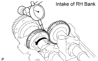
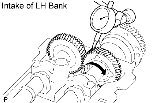
Check the gear backlash.
Install the drive gear to the camshaft timing tube.
Install the camshaft timing tube to the camshaft.
Install the camshaft and No. 2 camshaft without installing the camshaft sub-gear and front bearing cap.
Using a dial indicator, measure the backlash.
- Standard backlash:
- 0.020 to 0.200 mm (0.0008 to 0.0079 in.)
- Maximum backlash:
- 0.30 mm (0.0118 in.)
- If the backlash is greater than the maximum, replace the drive gear and No. 2 camshaft.
 |
Remove the camshaft and No. 2 camshaft.
Remove the camshaft timing tube from the camshaft.
Remove the drive gear from the camshaft timing tube.
| 2. INSPECT NO. 3 CAMSHAFT SUB-ASSEMBLY |
Inspect the circle runout.
Place the camshaft on V-blocks.
Using a dial indicator, measure the circle runout at the center journal.
- Maximum circle runout:
- 0.08 mm (0.0031 in.)
- If the circle runout is greater than the maximum, replace the No. 3 camshaft.
 |
Using a micrometer, measure the cam lobe height.
- Standard cam lobe height:
- 42.610 to 42.710 mm (1.6776 to 1.6815 in.)
- Minimum cam lobe height:
- 42.46 mm (1.6717 in.)
- If the cam lobe height is less than the minimum, replace the No. 3 camshaft.
 |
Inspect the journal diameter of the camshaft.
Using a micrometer, measure the journal diameter of the No. 3 camshaft for the camshaft bearing.
- Journal diameter:
- 26.954 to 26.970 mm (1.0612 to 1.0618 in.)
- If the journal diameter is not as specified, check the oil clearance.
Using a micrometer, measure the journal diameter for the camshaft timing tube.
- Journal diameter:
- 30.984 to 31.000 mm (1.2198 to 1.2205 in.)
- If the journal diameter is not as specified, check the oil clearance.

 |
Inspect the journal diameter of the camshaft timing tube.
Using a micrometer, measure the journal diameter.
- Journal diameter:
- 39.955 to 39.964 mm (1.5730 to 1.5734 in.)
- If the journal diameter is not as specified, check the oil clearance.
 |
Install the timing tube to the No. 3 camshaft, and check the timing tube turns smoothly.
- If necessary, replace the timing tube and No. 3 camshaft.
- If necessary, replace the timing tube and No. 3 camshaft.
 |
Check the oil clearance.
Install the camshaft timing tube to the No. 3 camshaft.
Clean the bearing caps and journals.
Check the bearings for flaking and scoring.
- If the bearings are damaged, replace the bearing caps and cylinder head as a set.
- If the bearings are damaged, replace the bearing caps and cylinder head as a set.
Place the No. 3 camshaft on the cylinder head.
Lay a strip of Plastigage across each of the journals.
Install the bearing caps.
- NOTICE:
- Be careful not to turn the camshaft.
Remove the bearing caps.
Measure the Plastigage at its widest point.
- Standard oil clearance:
Journal Oil clearance Camshaft journal 0.030 to 0.067 mm (0.0012 to 0.0026 in.) Camshaft timing tube journal 0.036 to 0.057 mm (0.0014 to 0.0022 in.)
- Maximum oil clearance:
Journal Oil clearance Camshaft journal 0.100 mm (0.0039 in.) Camshaft timing tube journal 0.075 mm (0.0030 in.)
- If the oil clearance is greater than the maximum, replace the No. 3 camshaft and timing tube. If necessary, replace the bearing caps and cylinder head as a set.
Completely remove the Plastigage.
Remove the camshaft.
Remove the camshaft timing tube from the No. 3 camshaft.
 |
Check the thrust clearance.
Install the camshaft timing tube to the No. 3 camshaft.
Install the No. 3 camshaft.
Using a dial indicator, measure the thrust clearance while moving the No. 3 camshaft back and forth.
- Standard thrust clearance:
- 0.060 to 0.100 mm (0.0024 to 0.0039 in.)
- Maximum thrust clearance:
- 0.13 mm (0.0051 in.)
- If the thrust clearance is greater than the maximum, replace the No. 3 camshaft. If necessary, replace the bearing caps and cylinder head as a set.
Remove the No. 3 camshaft.
Remove the camshaft timing tube from the No. 3 camshaft.
 |
Check the gear backlash.
Install the drive gear to the camshaft timing tube.
Install the camshaft timing tube to the No. 3 camshaft.
Install the No. 3 camshaft and No. 4 camshaft without installing the camshaft sub-gear and front bearing cap.
Using a dial indicator, measure the backlash.
- Standard backlash:
- 0.020 to 0.200 mm (0.0008 to 0.0079 in.)
- Maximum backlash:
- 0.30 mm (0.0188 in.)
- If the backlash is greater than the maximum, replace the drive gear and No. 4 camshaft.
 |
Remove the No. 3 camshaft and No. 4 camshaft.
Remove the camshaft timing tube from the No. 3 camshaft.
Remove the drive gear from the camshaft timing tube.
| 3. INSPECT CYLINDER HEAD SUB-ASSEMBLY |
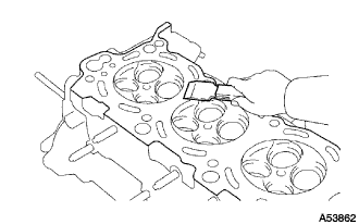
Clean the cylinder head.
Using a gasket scraper, remove all the gasket material from the cylinder block contact surface.
- NOTICE:
- Be careful not to scratch the cylinder block contact surface.
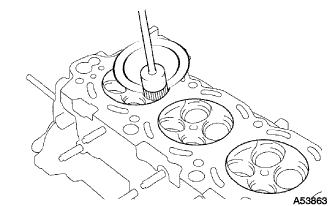
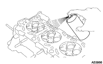
Using a wire brush, remove all the carbon from the combustion chambers.
- NOTICE:
- Be careful not to scratch the cylinder block contact surface.
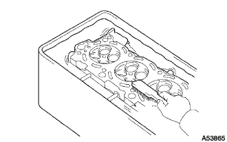
Using a valve guide bushing brush and solvent, clean all the guide bushes.
Using a soft brush and solvent, thoroughly clean the cylinder head.
 |
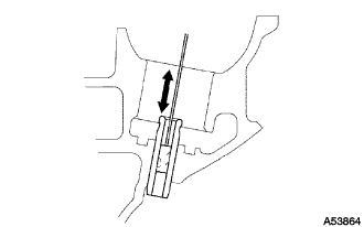
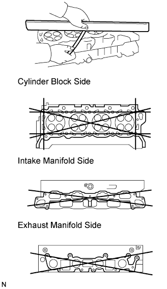
Inspect for flatness.
Using a precision straightedge and feeler gauge, measure the surfaces contacting the cylinder block and the manifolds for warpage.
- Maximum warpage:
Item Specified Condition Cylinder block surface 0.05 mm (0.0020 in.) Intake manifold surface 0.10 mm (0.0039 in.) Exhaust manifold surface 0.10 mm (0.0039 in.)
 |
Inspect the cylinder head for cracks.
Using a dye penetrant, check the combustion chamber, intake ports, exhaust ports and cylinder block surface for cracks.
- If the cylinder head is cracked, replace it.
- If the cylinder head is cracked, replace it.
 |
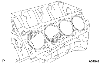
| 4. INSPECT CYLINDER BLOCK SUB-ASSEMBLY |
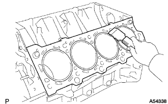
Clean the cylinder block.
Using a gasket scraper, remove all the gasket material from the top surface of the cylinder block.
Using a soft brush and solvent, thoroughly clean the cylinder block.
- NOTICE:
- If the cylinder is washed at high temperatures, the cylinder liner sticks out beyond the cylinder block. Always wash the cylinder block at a temperature of 45°C (113°F) or less.
 |
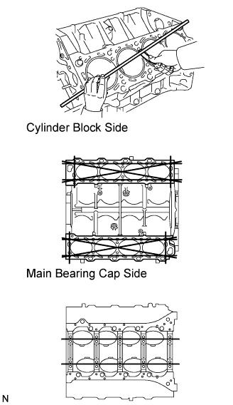
Inspect for flatness.
Using a precision straightedge and feeler gauge, measure the surfaces contacting the cylinder head and main bearing cap for warpage.
- Maximum warpage:
- 0.07 mm (0.0028 in.)
 |
Visually check the cylinder for vertical scratches.
If deep scratches are present, replace the cylinder block.
 |
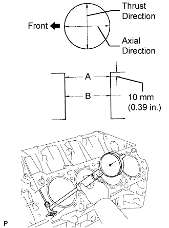
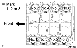
Inspect the cylinder bore diameter.
- HINT:
- There are 3 sizes of the standard cylinder bore diameter, marked "1", "2" and "3" accordingly. The mark is stamped on the top of the cylinder block.
- If deep scratches are present, replace the cylinder block.
Using a cylinder gauge, measure the cylinder bore diameter at positions A and B in the thrust and axial directions.
- Standard diameter:
Number Mark Specified Condition Mark 1 91.000 to 91.008 mm (3.5827 to 3.5830 in.) Mark 2 91.008 to 91.021 mm (3.5830 to 3.5835 in.) Mark 3 91.021 to 91.029 mm (3.5835 to 3.5838 in.)
- Maximum diameter:
- 91.149 mm (3.5885 in.)
- HINT:
- If the wear is less than 0.2 mm (0.008 in.), using a ridge reamer, grind the top of the cylinder.

 |
| 5. INSPECT PISTON SUB-ASSEMBLY WITH PIN |
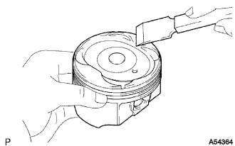
Clean the piston.
Using a gasket scraper, remove the carbon from the piston top.
Using a groove cleaning tool or broken ring, clean the piston ring grooves.
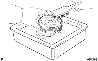
Using solvent and a brush, thoroughly clean the piston.
- NOTICE:
- Do not use a wire brush.
 |
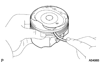
Inspect the piston oil clearance.
- HINT:
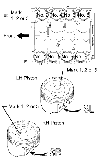
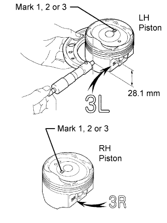
- There are 3 standard diameter sizes, marked "1", "2" and "3". The mark is stamped on the piston top.
Using a micrometer, measure the piston diameter at right angles to the piston pin center line, 28.1 mm (1.106 in.) from the piston head.
- Piston diameter:
Number Mark Specified Condition Mark 1 90.910 to 90.920 mm (3.5791 to 3.5795 in.) Mark 2 90.920 to 90.928 mm (3.5795 to 3.5798 in.) Mark 3 90.928 to 90.938 mm (3.5798 to 3.5802 in.)
Measure the cylinder bore diameter in the thrust directions.
Subtract the piston diameter measurement from the cylinder bore diameter measurement.
- Standard oil clearance:
- 0.080 to 0.101 mm (0.0031 to 0.0040 in.)
- Maximum oil clearance:
- 0.101 mm (0.0040 in.)
- HINT:
- Use a new cylinder block
- Use a piston with the same number mark as the cylinder diameter marked on the cylinder block.
- The shape of the piston varies for the LH and RH banks. The LH piston is marked with "3L" and the RH piston is marked with "3R".
 |
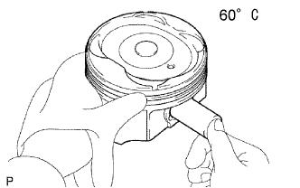
Inspect the piston pin fit.
At 60°C (140°F), check that the piston pin can be pushed into the piston pin hole with your thumb.
 |
Using a micrometer, measure the piston pin diameter.
- Piston pin diameter:
- 21.997 to 22.006 mm (0.8660 to 0.8664 in.)
 |
| 6. INSPECT PISTON RING SET |
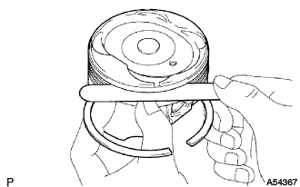
Inspect the piston ring groove clearance.
Using a feeler gauge, measure the clearance between a new piston ring and the wall of the ring groove.
- Ring groove clearance:
Piston Ring Specified Condition No. 1 0.030 to 0.080 mm (0.0012 to 0.0031 in.) No. 2 0.020 to 0.060 mm (0.0008 to 0.0024 in.)
 |
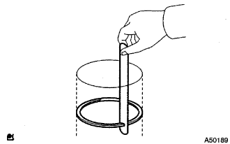
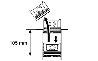
Inspect the piston ring end gap.
Insert the piston ring into the cylinder bore.
Using a piston, push the piston ring a little beyond the bottom of the ring travel 105 mm (4.13 in.) from the top of the cylinder block.
Using a feeler gauge, measure the end gap.
- Standard end gap:
End Gap Specified Condition No. 1 piston ring 0.300 to 0.400 mm (0.0118 to 0.0157 in.) No. 2 piston ring 0.400 to 0.500 mm (0.0157 to 0.0197 in.) Oil ring (Side rail) 0.150 to 0.400 mm (0.0059 to 0.0157 in.)
- Maximum end gap:
End Gap Specified Condition No. 1 piston ring 1.10 mm (0.0433 in.) No. 2 piston ring 1.20 mm (0.0472 in.) Oil ring (Side rail) 1.10 mm (0.0433 in.)
 |
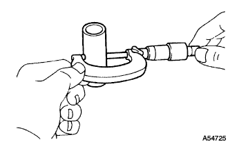
| 7. INSPECT CONNECTING ROD SUB-ASSEMBLY |
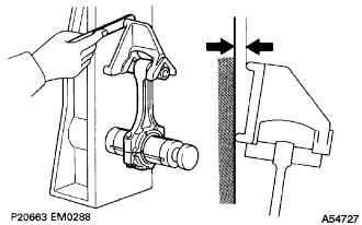
Using a rod aligner and feeler gauge, check the connecting rod alignment.
Check if the connecting rod is bent.
- Maximum bend:
- 0.05 mm (0.0020 in.) per 100 mm (3.94 in.)
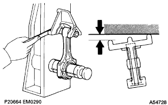
Check if the connecting rod is twisted.
- Maximum twist:
- 0.15 mm (0.0059 in.) per 100 mm (3.94 in.)
 |
| 8. INSPECT PISTON PIN OIL CLEARANCE |
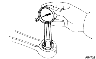
Inspect the piston pin oil clearance.
Using a caliper gauge, measure the inside diameter of the connecting rod bushing.
- Bushing inside diameter:
- 22.005 to 22.014 mm (0.8663 to 0.8667 in.)
Subtract the piston pin diameter measurement from the bush inside diameter measurement.
- Standard oil clearance:
- 0.005 to 0.011 mm (0.0002 to 0.0004 in.)
- Maximum oil clearance:
- 0.05 mm (0.0020 in.)
 |
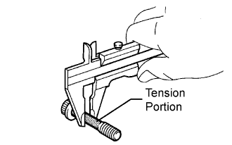
| 9. INSPECT CONNECTING ROD BOLT |
Using a vernier caliper, measure the tension portion of the connecting rod bolt.
- Standard diameter:
- 7.200 to 7.300 mm (0.2835 to 0.2874 in.)
- Maximum diameter:
- 7.00 mm (0.2756 in.)
 |
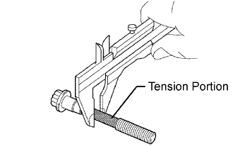
| 10. INSPECT CRANKSHAFT BEARING CAP BOLT |
Using a vernier caliper, measure the tension portion diameter of the main bearing cap bolt.
- Standard diameter:
- 7.500 to 7.600 mm (0.2953 to 0.2992 in.)
- Maximum diameter:
- 7.20 mm (0.2835 in.)
 |
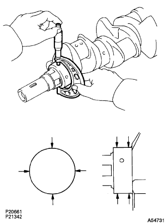
| 11. INSPECT CRANKSHAFT |
Inspect for circle runout.
Place the crankshaft on V-blocks.
Using a dial indicator, measure the circle runout at the center journal.
- Maximum circle runout:
- 0.08 mm (0.0031 in.)
 |
Inspect the main journals and crank pins.
Using a micrometer, measure the diameter of each main journal and crank pin.
- Main journal diameter:
- 66.988 to 67.000 mm (2.6373 to 2.6378 in.)
- Crank pin diameter:
- 51.982 to 52.000 mm (2.0465 to 2.0472 in.)
Check each main journal and crank pin for taper and out of round as shown in the illustration.
- Maximum taper and out of round:
- 0.02 mm (0.0008 in.)
 |