Engine Unit -- Disassembly |
- HINT:
- Thoroughly clean all parts to be assembled.
- Before installing the parts, apply new engine oil to all sliding and rotating surfaces.
- Replace all gaskets, O-rings and oil seals with new parts.
| 1. REMOVE SPARK PLUG |
| 2. REMOVE OIL FILLER CAP HOUSING |
Remove the 2 nuts and housing.
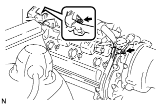
| 3. REMOVE CYLINDER HEAD COVER SUB-ASSEMBLY RH |
Remove the bolt, and disconnect the wire clamp bracket from the camshaft bearing cap.
 |
Remove the bolt, and disconnect the engine wire protector from the cylinder head cover.
Remove the 9 bolts, 9 seal washers and cylinder head cover.
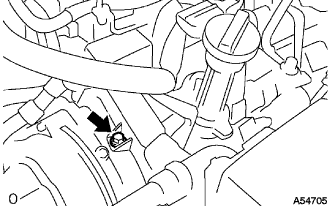
| 4. REMOVE CYLINDER HEAD COVER SUB-ASSEMBLY LH |
Remove the bolt, and disconnect the wire clamp bracket from the camshaft bearing cap.
 |
Remove the 9 bolts, 9 seal washers and cylinder head cover.
| 5. REMOVE NO. 1 IDLER PULLEY BRACKET SUB-ASSEMBLY |
Remove the bolt, pulley plate and idler pulley.
 |
Remove the 2 bolts and bracket.
 |
| 6. REMOVE NO. 2 IDLER PULLEY SUB-ASSEMBLY |
Remove the pulley bolt, cover plate and idler pulley.
 |
| 7. REMOVE NO. 2 TIMING BELT COVER SUB-ASSEMBLY |
Remove the 2 bolts and timing belt cover.
 |
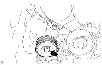
| 8. REMOVE V-RIBBED BELT TENSIONER ASSEMBLY |
Remove the bolt, 2 nuts and belt tensioner.
 |
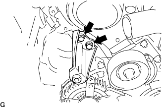
| 9. REMOVE IDLER PULLEY ASSEMBLY |
Remove the 2 bolts, 2 nuts and idler pulley.
 |
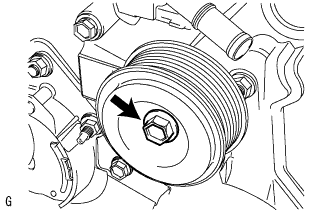
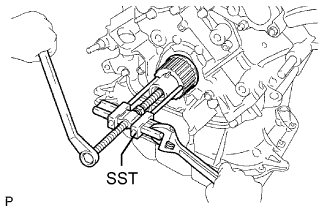
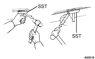
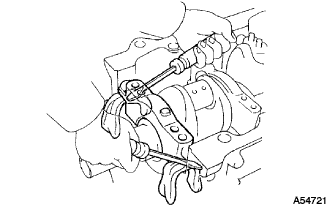
| 10. REMOVE CRANKSHAFT DAMPER SUB-ASSEMBLY |
Using SST, remove the damper bolt.
- SST
- 09213-70011
09330-00021
 |
Using SST, remove the damper.
- SST
- 09950-50013(09951-05010,09952-05010,09953-05010,09953-05020,09954-05021)
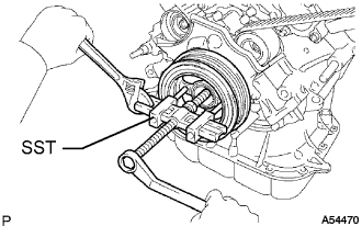 |
| 11. REMOVE NO. 1 TIMING BELT COVER |
Remove the 4 bolts and timing belt cover.
| 12. REMOVE NO. 1 CRANKSHAFT POSITION SENSOR PLATE |
| 13. REMOVE TIMING GEAR COVER SPACER |
| 14. REMOVE TIMING BELT |
If planning to reuse the belt, check the installation marks on the timing belt.
Check that there are 3 installation marks on the belt by turning the crankshaft as shown in the illustration.
If the installation marks have disappeared, place new installation marks on the belt before removing each part.
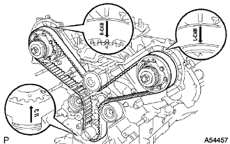 |
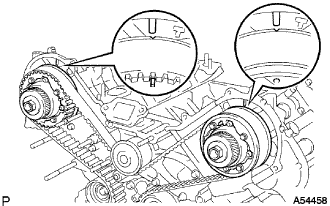
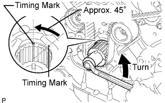
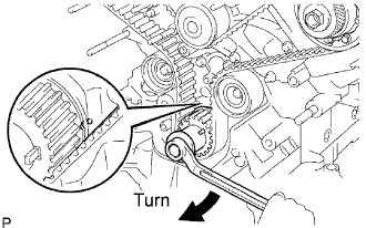
Set the No. 1 cylinder to approximately 45° BTDC/compression.
Using the crankshaft damper bolt, turn the crankshaft to align the timing marks of the crankshaft timing pulley and oil pump body.
Check that the timing marks of the camshaft timing pulleys and timing belt plates are aligned. If not, turn the crankshaft 1 revolution (360°).
Using the crankshaft damper bolt, turn the crankshaft counterclockwise by approximately 45°.
- NOTICE:
- With the timing belt disengaged, the crankshaft damper must be at the correct angle to avoid damage in a later step.
 |
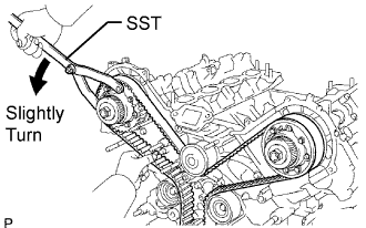
Alternately loosen the 2 bolts. Then remove the 2 bolts, belt tensioner and dust boot.
Using SST, loosen the tension between the camshaft timing pulley (RH bank) and crankshaft timing pulley by slightly turning the camshaft timing pulley (RH bank) counterclockwise.
- SST
- 09960-10010(09962-01000,09963-00350)
 |
Disconnect the belt from the timing belt idler No. 1, and remove the belt.
| 15. REMOVE NO. 1 TIMING BELT IDLER SUB-ASSEMBLY |
Using a 10 mm hexagon wrench, remove the bolt, idler and plate washer.
| 16. REMOVE NO. 2 TIMING BELT IDLER SUB-ASSEMBLY |
Remove the bolt and idler.
| 17. REMOVE CRANKSHAFT TIMING PULLEY |
Using SST, remove the timing pulley.
- SST
- 09950-50013(09951-05010,09952-05010,09953-05010,09953-05020,09954-05010)
- NOTICE:
- Do not turn the timing pulley.
 |
| 18. REMOVE CAMSHAFT TIMING PULLEY |
Remove the 4 bolts and timing pulley.
 |
| 19. REMOVE CAMSHAFT TIMING PULLEY SUB-ASSEMBLY LH |
 |
| 20. REMOVE CAMSHAFT |
- NOTICE:
- Since the thrust clearance of the camshaft is small, the camshaft must be kept level while it is being removed. If the camshaft is not kept level, the portion of the cylinder head receiving the shaft thrust may crack or be damaged, causing the camshaft to seize or break. To avoid this, the following steps should be carried out.
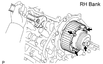
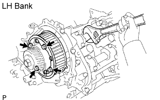
Remove the camshafts of the RH bank.
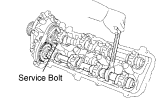
Bring the service bolt hole of the sub gear upward by turning the hexagon head portion of the No. 2 camshaft with a wrench.
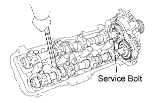
Secure the sub gear to the main gear with a service bolt.
- Recommended service bolt:
Thread diameter Thread pinch Bolt length 6 mm 1.0 mm 16 to 20 mm (0.63 to 0.79 in.)
- HINT:
- When removing the camshaft, make sure that the torsional spring force of the sub gear has been eliminated by the above operation.
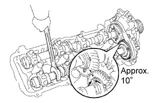
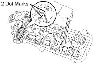
Set a wrench to the hexagon head portion of the No. 2 camshaft. Rotate the wrench so that the timing mark (1 dot mark) on the camshaft main gear is moved approximately 10°, as shown in the illustration.
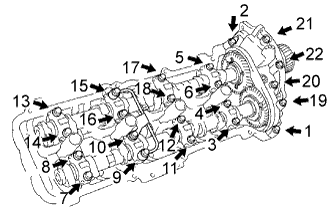
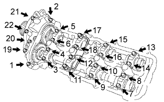
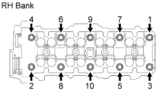
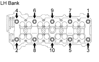
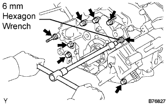
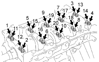
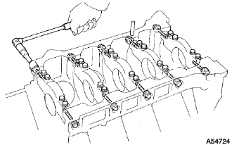
Uniformly loosen the 22 bearing cap bolts in several passes in the sequence shown in the illustration.
Remove the 22 bearing cap bolts, 4 seal washers, oil feed pipe, 9 bearing caps, camshaft housing plug, oil control valve filter and 2 camshafts.
 |
| 21. REMOVE NO. 2 CAMSHAFT |
- NOTICE:
- Since the thrust clearance of the camshaft is small, the camshaft must be kept level while it is being removed. If the camshaft is not kept level, the portion of the cylinder head receiving the shaft thrust may crack or be damaged, causing the camshaft to seize or break. To avoid this, the following steps should be carried out.
Bring the service bolt hole of the sub gear upward by turning the hexagon head portion of the No. 2 camshaft with a wrench.
|
Secure the sub gear to the main gear with a service bolt.
- Recommended service bolt:
Thread diameter Thread pinch Bolt length 6 mm 1.0 mm 16 to 20 mm (0.63 to 0.79 in.)
- HINT:
- When removing the camshaft, make sure that the torsional spring force of the sub gear has been eliminated by the above operation.
Set a wrench to the hexagon head portion of the No. 2 camshaft. Rotate the wrench so that the timing mark (1 dot mark) on the camshaft main gear is moved approximately 10°, as shown in the illustration.
|
Uniformly loosen the 22 bearing cap bolts in several passes in the sequence shown in the illustration.
|
Remove the 22 bearing cap bolts, 4 seal washers, oil feed pipe, 9 bearing caps, camshaft housing plug, oil control valve filter and 2 camshafts.
- NOTICE:
- Do not forcibly pry the camshaft with a tool.
- Do not damage the reception part of the thrust on the cylinder head side.
| 22. REMOVE NO. 3 CAMSHAFT SUB-ASSEMBLY |
- NOTICE:
- Since the thrust clearance of the camshaft is small, the camshaft must be kept level while it is being removed. If the camshaft is not kept level, the portion of the cylinder head receiving the shaft thrust may crack or be damaged, causing the camshaft to seize or break. To avoid this, the following steps should be carried out.
Remove the camshafts of the LH bank.
Bring the service bolt hole of the sub gear upward by turning the hexagon head portion of the exhaust No. 4 camshaft with a wrench.
Secure the sub gear to the main gear with a service bolt.
- Recommended service bolt:
Thread diameter Thread pinch Bolt length 6 mm 1.0 mm 16 to 20 mm (0.63 to 0.79 in.)
- HINT:
- When removing the camshaft, make sure that the torsional spring force of the sub gear has been eliminated by the above operation.
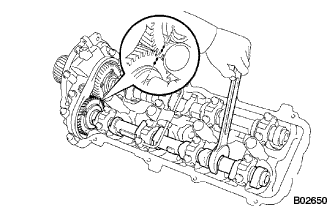
Set a wrench to the hexagon head portion of the No. 4 camshaft. Rotate the wrench so that the timing marks (2 dot marks each) on the camshaft drive and driven main gears are aligned, as shown in the illustration.
Uniformly loosen the 22 bearing cap bolts in several passes, in the sequence shown in the illustration.
Remove the 22 bearing cap bolts, 4 seal washers, oil feed pipe, 9 bearing caps, camshaft housing plug, oil control valve filter and 2 camshafts.
- NOTICE:
- Do not forcibly pry the camshaft with a tool.
- Do not damage the reception part of the thrust on the cylinder head side.
 |
| 23. REMOVE NO. 4 CAMSHAFT SUB-ASSEMBLY |
- NOTICE:
- Since the thrust clearance of the camshaft is small, the camshaft must be kept level while it is being removed. If the camshaft is not kept level, the portion of the cylinder head receiving the shaft thrust may crack or be damaged, causing the camshaft to seize or break. To avoid this, the following steps should be carried out.
Bring the service bolt hole of the sub gear upward by turning the hexagon head portion of the exhaust camshaft with a wrench.
|
Secure the sub gear to the main gear with a service bolt.
- Recommended service bolt:
Thread diameter Thread pinch Bolt length 6 mm 1.0 mm 16 to 20 mm (0.63 to 0.79 in.)
- HINT:
- When removing the camshaft, make sure that the torsional spring force of the sub gear has been eliminated by the above operation.
Set a wrench to the hexagon head portion of the No. 4 camshaft. Rotate the wrench so that the timing marks (2 dot marks each) on the camshaft drive and driven main gears are aligned, as shown in the illustration.
 |
Uniformly loosen the 22 bearing cap bolts in several passes in the sequence shown in the illustration.
|
Remove the 22 bearing cap bolts, 4 seal washers, oil feed pipe, 9 bearing caps, camshaft housing plug, oil control valve filter and 2 camshafts.
- NOTICE:
- Do not forcibly pry the camshaft with a tool.
- Do not damage the reception part of the thrust on the cylinder head side.
| 24. REMOVE SEMICIRCULAR PLUG |
| 25. REMOVE REAR NO. 2 TIMING BELT PLATE RH |
Remove the 2 bolts and timing belt plate.
| 26. REMOVE REAR TIMING BELT PLATE RH |
Remove the bolt, stud bolt and timing belt plate.
| 27. REMOVE REAR NO. 2 TIMING BELT PLATE LH |
Remove the 2 bolts and timing belt plate.
| 28. REMOVE REAR TIMING BELT PLATE LH |
Remove the bolt, stud bolt and timing belt plate.
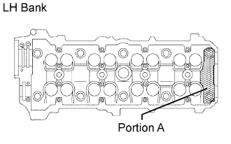
| 29. REMOVE CYLINDER HEAD SUB-ASSEMBLY |
Uniformly loosen 10 cylinder head bolts on one side of each cylinder head in several passes, in the sequence shown in the illustration.
- NOTICE:
- Cylinder head warpage or cracking could result from removing bolts in the incorrect order.
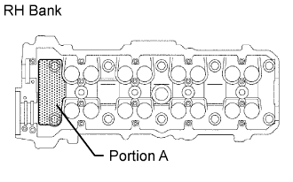
- Be careful not to drop the plate washer for the cylinder head bolt into portion A of the cylinder head. If dropped into portion A, the plate washer will pass through the cylinder head and cylinder block into the oil pan.
  |
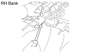
Lift the cylinder head from the dowels on the cylinder block, and place the cylinder head on wooden blocks on a bench.
- HINT:
- If the cylinder head cannot be removed, pry between the cylinder head and cylinder block with a screwdriver.
- NOTICE:
- Be careful not to damage the contact surfaces of the cylinder head and cylinder block.
 |
| 30. REMOVE CYLINDER HEAD LH |
Uniformly loosen 10 cylinder head bolts on one side of each cylinder head in several passes, in the sequence shown in the illustration.
- NOTICE:
- Cylinder head warpage or cracking could result from removing bolts in the incorrect order.
- Be careful not to drop the plate washer for the cylinder head bolt into portion A of the cylinder head. If dropped into portion A, the plate washer will pass through the cylinder head and cylinder block into the oil pan.
  |
Lift the cylinder head from the dowels on the cylinder block, and place the cylinder head on wooden blocks on a bench.
- HINT:
- If the cylinder head cannot be removed, pry between the cylinder head and cylinder block with a screwdriver.
- NOTICE:
- Be careful not to damage the contact surfaces of the cylinder head and cylinder block.
 |
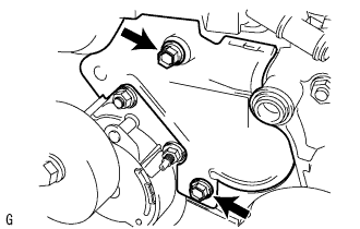
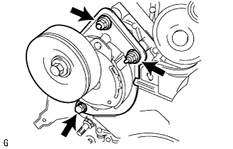
| 31. REMOVE WATER PUMP ASSEMBLY |
Remove the 5 bolts, 2 stud bolts, nut, water pump and gasket.
| 32. REMOVE NO. 2 OIL PAN SUB-ASSEMBLY |
Remove the 12 bolts and 2 nuts.
 |
Insert the blade of SST between the No. 1 and No. 2 oil pans, cut through the sealer and remove the No. 2 oil pan.
- SST
- 09032-00100
- NOTICE:
- Be careful not to damage the contact surface of the oil pans.
| 33. REMOVE OIL PAN BAFFLE PLATE |
Remove the 4 bolts, 2 nuts and baffle plate.
 |
| 34. REMOVE OIL PAN SUB-ASSEMBLY |
Remove the 18 bolts, 2 nuts and oil pan.
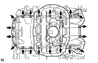 |
Using a screwdriver, remove the oil pan by prying the areas between the cylinder block and oil pan shown in the illustration.
- NOTICE:
- Be careful not to damage the contact surfaces of the cylinder block and oil pan.
| 35. REMOVE OIL STRAINER SUB-ASSEMBLY |
Remove the 2 bolts, 2 nuts, oil strainer and gasket.
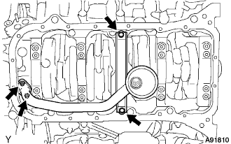 |
| 36. REMOVE OIL PUMP ASSEMBLY |
Remove the stud bolt and 7 bolts.
- HINT:
- Use a 6 mm hexagon wrench for the hexagon head bolt.
 |
Using a screwdriver, remove the oil pump by prying the areas between the oil pump and cylinder block shown in the illustration.
 |
Remove the O-ring from the cylinder block.
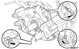
| 37. REMOVE ENGINE REAR OIL SEAL RETAINER |
Remove the 7 bolts.
 |
Using a screwdriver, remove the oil seal retainer by prying the portions between the oil seal retainer and crankshaft bearing cap.
Remove the O-ring.
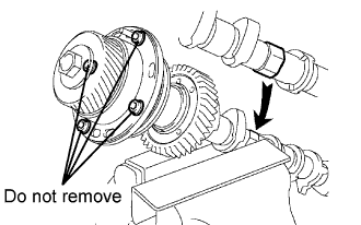
| 38. REMOVE CAMSHAFT TIMING TUBE ASSEMBLY |
Mount the hexagon head portion of the camshaft in a vise.
- NOTICE:
- Be careful not to damage the camshaft.
- Do not remove the 4 bolts shown in the illustration. The bolts determine the backlash of the gear in the timing tube. If any of the bolts are removed, install a new timing tube assembly.
 |
Remove the screw plug and seal washer.
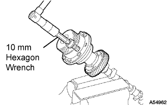 |
Using a 10 mm hexagon wrench, remove the bolt.
Pull out the timing tube and drive gear from the camshaft.
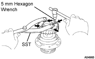
Using SST and a 5 mm hexagon wrench, remove the 4 bolts, drive gear and oil seal.
- SST
- 09960-10010(09962-01000,09963-00500)
- NOTICE:
- Be careful not to damage the timing tube.
 |
| 39. REMOVE CYLINDER BLOCK WATER DRAIN COCK SUB-ASSEMBLY |
Remove the RH and LH drain unions.
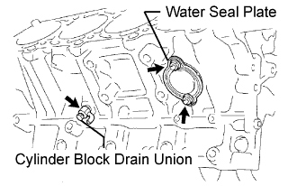 |
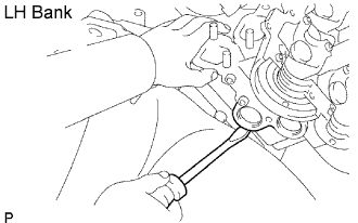
| 40. REMOVE WATER SEAL PLATE |
Remove the 2 nuts.
Pry out the seal plate.
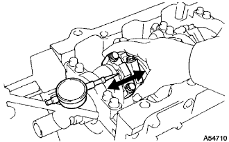
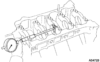
| 41. INSPECT CONNECTING ROD THRUST CLEARANCE |
Using a dial indicator, measure the thrust clearance while moving the connecting rod back and forth.
- Standard thrust clearance:
- 0.160 to 0.290 mm (0.0063 to 0.0138 in.)
- maximum thrust clearance:
- 0.35 mm (0.0138 in.)
- Connecting rod thickness:
- 22.880 to 22.920 mm (0.9008 to 0.9024 in.)
 |
| 42. INSPECT CONNECTING ROD OIL CLEARANCE |
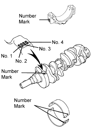
Check the matchmarks on the connecting rod and cap to ensure correct reassembly.
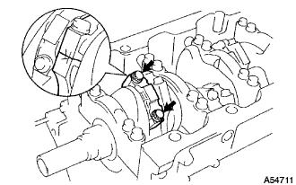 |
Remove the 2 connecting rod cap bolts.
Using the removed connecting rod cap bolts, remove the connection rod cap and lower bearing by wiggling the connecting rod cap right and left.
- HINT:
- Keep the lower bearing inserted with the connecting rod cap.
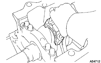 |
Clean the crank pin and bearing.
Check the crank pin and bearing for pitting and scratches. If the crank pin or bearing is damaged, replace the bearings. If necessary, replace the crankshaft.
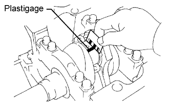
Lay a strip of Plastigage across the crank pin.
 |
Install the connecting rod cap with the 2 bolts.
 |
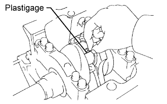
Remove the 2 bolts, connecting rod cap and lower bearing.
Measure the Plastigage at its widest point.
- Standard oil clearance:
- 0.021 to 0.047 mm (0.0008 to 0.0019 in.)
- Maximum oil clearance:
- 0.065 mm (0.0026 in.)
- HINT:
- If replacing a standard bearing, replace it with one that has the same number. If the number of the bearing cannot be determined, select the correct bearing by adding together the numbers imprinted on the connecting rod cap and crankshaft, and then select the bearing with the same number as the total. There are 6 sizes of standard bearings, marked 2, 3, 4, 5, 6 and 7.
- Standard Bearings:
Item Number Mark Connecting rod 1 2 1 2 3 Crankshaft 1 2 1 3 2 1 Use bearing 2 3 4
- Standard Bearings:
Item Number Mark Connecting rod 2 3 4 3 4 Crankshaft 3 2 1 3 2 3 Use bearing 5 6 7
- EXAMPLE:
- Connecting rod cap "3" + Crankshaft "1" = "4" (Use bearing "4")
- Connecting rod big end inside diameter:
Number Mark Specified Condition Mark 1 55.000 to less than 55.006 mm (2.1654 to less than 2.1656 in.) Mark 2 55.006 to less than 55.012 mm (2.1656 to less than 2.1658 in.) Mark 3 55.012 to less than 55.018 mm (2.1658 to less than 2.1661 in.) Mark 4 55.018 to less than 55.024 mm (2.1661 to less than 2.1663 in.)
- Crankshaft crank pin diameter:
Number Mark Specified Condition Mark 1 51.994 to less than 52.000 mm (2.0470 to less than 2.0472 in.) Mark 2 51.988 to less than 51.994 mm (2.0468 to less than 2.0470 in.) Mark 3 51.982 to less than 51.988 mm (2.0465 to less than 2.0468 in.)
- Standard sized bearing center wall thickness:
Number Mark Specified Condition Mark 2 1.487 to less than 1.490 mm (0.0585 to less than 0.0587 in.) Mark 3 1.490 to less than 1.493 mm (0.0587 to less than 0.0588 in.) Mark 4 1.493 to less than 1.496 mm (0.0588 to less than 0.0589 in.) Mark 5 1.496 to less than 1.499 mm (0.0589 to less than 0.0590 in.) Mark 6 1.499 to less than 1.502 mm (0.0590 to less than 0.0591 in.) Mark 7 1.502 to less than 1.505 mm (0.0591 to less than 0.0593 in.)
  |
Completely remove the Plastigage.
| 43. INSPECT CRANKSHAFT THRUST CLEARANCE |
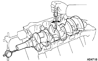
Using a dial indicator, measure the thrust clearance while prying the crankshaft back and forth with a screwdriver.
- Standard thrust clearance:
- 0.020 to 0.220 mm (0.0008 to 0.0087 in.)
- Maximum thrust clearance:
- 0.30 mm (0.0118 in.)
- Thrust washer thickness:
- 2.440 to 2.490 mm (0.0961 to 0.0980 in.)
 |
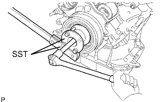
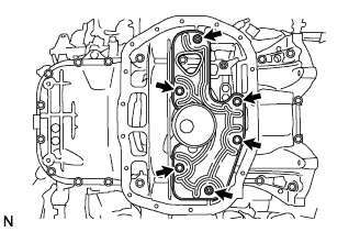
| 44. INSPECT CRANKSHAFT OIL CLEARANCE |
Remove the 10 crankshaft bearing cap bolts.
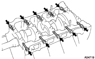 |
Uniformly loosen and remove the 20 crankshaft bearing cap bolts in the sequence shown in the illustration.
 |
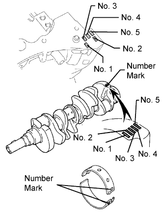
Using 2 screwdrivers, pry out the crankshaft bearing cap, and remove the 5 crankshaft bearing caps, 5 lower bearings and 2 lower thrust washers (No. 3 crankshaft bearing cap only).
- NOTICE:
- Be careful not to damage the cylinder block.
- HINT:
- Keep the lower bearing and cap together.
- Be sure to arrange the bearing caps and lower thrust washers in such a way that they can be reinstalled exactly as before.
 |
Lift out the crankshaft.
Remove the 2 upper thrust washers.
- HINT:
- Be sure to arrange the removed upper thrust washers in such a way that they can be reinstalled exactly as before.
- Keep the upper bearings together with the cylinder block.
Clean each crankshaft journal and bearing.
Check each crankshaft journal and bearing for pitting and scratches.
If the journal or bearing is damaged, replace the bearings. If necessary, replace the crankshaft.
Install the 10 crankshaft bearings and 5 crankshaft bearing caps with the 30 bolts. Do not install the crankshaft.
 |
Using a cylinder gauge, measure the inside diameter of the crankshaft bearing.
- Bearing inside diameter:
- 66.986 to 67.000 mm (2.6372 to 2.6378 in.)
 |
Measure the diameter of the crankshaft journal.
Subtract the crankshaft journal diameter measurement from the crankshaft bearing inside diameter measurement.
- Standard clearance:
Number Mark Specified Condition No. 1 and No. 5 0.017 to 0.033 mm (0.0007 to 0.0013 in.) Others 0.029 to 0.045 mm (0.0011 to 0.0018 in.)
- Maximum clearance:
Number Mark Specified Condition No. 1 and No. 5 0.043 mm (0.0017 in.) Others 0.055 mm (0.0022 in.)
- HINT:
- If replacing a standard bearing, replace it with one that has the same number. If the number of the bearing cannot be determined, select the correct bearing by adding together the numbers imprinted on the cylinder block and crankshaft, and then refer to the table below for the appropriate bearing number. There are 5 sizes of standard bearings. For No. 1 and No. 5 position bearings, use bearings marked 3, 4, 5, 6 and 7. For other position bearings, use bearings marked 1, 2, 3, 4 and 5.
B = Crankshaft- No. 1, No. 5:
(A) + (B) Upper Lower 0 to 5 3 3 6 to 8 3 4 9 to 11 4 4 12 to 14 4 5 15 to 17 5 5 18 to 20 5 6 21 to 23 6 6 24 to 26 6 7 27 to 28 7 7
- EXAMPLE:
- Cylinder block "08" + Crankshaft "06" = Total number 14 (Use bearing "4" (Upper), "5" (Lower))
- Others:
(A) + (B) Upper Lower 0 to 5 1 1 6 to 8 1 2 9 to 11 2 2 12 to 14 2 3 15 to17 3 3 18 to 20 3 4 21 to 23 4 4 24 to 26 4 5 27 to 28 5 5
- EXAMPLE:
- Cylinder block "08" + Crankshaft "06" = Total number 14 (Use bearing "2" (Upper), "3" (Lower))
- Cylinder block crankshaft journal bore diameter (A):
Number Mark Specified Condition Mark 00 72.000 mm (2.8346 in.) Mark 01 72.001 mm (2.8347 in.) Mark 02 72.002 mm (2.8347 in.) Mark 03 72.003 mm (2.8348 in.) Mark 04 72.004 mm (2.8348 in.) Mark 05 72.005 mm (2.8348 in.) Mark 06 72.006 mm (2.8349 in.) Mark 07 72.007 mm (2.8349 in.) Mark 08 72.008 mm (2.8350 in.) Mark 09 72.009 mm (2.8350 in.) Mark 10 72.010 mm (2.8350 in.) Mark 11 72.011 mm (2.8351 in.) Mark 12 72.012 mm (2.8351 in.) Mark 13 72.013 mm (2.8352 in.) Mark 14 72.014 mm (2.8352 in.) Mark 15 72.015 mm (2.8352 in.) Mark 16 72.016 mm (2.8353 in.)
- Crankshaft journal diameter (B):
Number Mark Specified Condition Mark 00 67.000 mm (2.6378 in.) Mark 01 66.999 mm (2.6378 in.) Mark 02 66.998 mm (2.6377 in.) Mark 03 66.997 mm (2.6377 in.) Mark 04 66.996 mm (2.6376 in.) Mark 05 66.995 mm (2.6376 in.) Mark 06 66.994 mm (2.6376 in.) Mark 07 66.993 mm (2.6375 in.) Mark 08 66.992 mm (2.6375 in.) Mark 09 66.991 mm (2.6374 in.) Mark 10 66.990 mm (2.6374 in.) Mark 11 66.989 mm (2.6374 in.) Mark 12 66.988 mm (2.6373 in.)
- Standard bearing center wall thickness:
Number Mark Specified Condition Mark 3 2.492 to less than 2.495 mm (0.0981 to less than 0.0982 in.) Mark 4 2.495 to less than 2.498 mm (0.0982 to less than 0.0983 in.) Mark 5 2.498 to less than 2.501 mm (0.0983 to less than 0.0985 in.) Mark 6 2.501 to less than 2.504 mm (0.0985 to less than 0.0986 in.) Mark 7 2.504 to less than 2.507 mm (0.0986 to less than 0.0987 in.)
- Others:
Number Mark Specified Condition Mark 1 2.486 to less than 2.489 mm (0.0979 to less than 0.0980 in.) Mark 2 2.489 to less than 2.492 mm (0.0980 to less than 0.0981 in.) Mark 3 2.492 to less than 2.495 mm (0.0981 to less than 0.0982 in.) Mark 4 2.495 to less than 2.498 mm (0.0982 to less than 0.0983 in.) Mark 5 2.498 to less than 2.501 mm (0.0983 to less than 0.0985 in.)
 |
Remove the 30 bolts, 5 crankshaft bearing caps and 5 lower crankshaft bearings.
 |
Remove the 5 upper crankshaft bearings from the cylinder block.
- HINT:
- Be sure to arrange the bearing caps, bearings and thrust washers in such a way that they can be reinstalled exactly as before.
| 45. REMOVE PISTON AND CONNECTING ROD |
Using a ridge reamer, remove all the carbon from the top of the cylinder.
 |
Push the piston, connecting rod assembly and upper bearing through the top of the cylinder block.
- HINT:
- Keep the bearings, connecting rod and cap together.
- Be sure to arrange the removed piston and connecting rod assemblies in such a way that they can be reinstalled exactly as before.
| 46. REMOVE PISTON SUB-ASSEMBLY WITH PIN |
Check the piston and piston pin.
Try to move the piston back and forth on the piston pin.
If any movement is felt, replace the piston and pin with a new piston and pin set.
 |
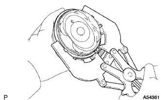
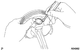
Using a piston ring expander, remove the No. 1 and No. 2 piston rings.
- HINT:
- Be sure to arrange the removed piston rings in such a way that they can be reinstalled exactly as before.
 |
Remove the 2 side rails and expander by hand.
Using a small screwdriver, pry out the 2 snap rings.
 |
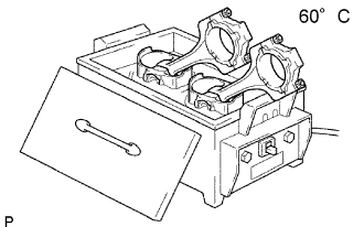
Gradually heat the piston to approximately 60°C (140°F).
 |
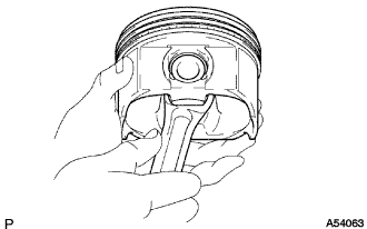
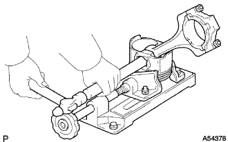
Using a plastic-faced hammer and brass bar, lightly tap out the piston and pin. Then remove the connecting rod.
- HINT:
- The piston and pin are a matched set.
- Be sure to arrange the removed pistons, pins, rings, connecting rods and bearings in such a way that the parts can be reinstalled exactly as before.
 |