Dtc P0031 Oxygen Sensor Heater Control Circuit Low (Bank 1 Sensor 1)
Engine. Lexus Gs430, Gs300. Uzs190 Grs190
DESCRIPTION
MONITOR DESCRIPTION
WIRING DIAGRAM
INSPECTION PROCEDURE
INSPECT HEATED OXYGEN SENSOR (HEATER RESISTANCE)
INSPECT INTEGRATION RELAY (EFI MAIN)
CHECK ECM (HT1A, HT2A, HT1B, HT2B VOLTAGE)
CHECK WIRE HARNESS (HEATED OXYGEN SENSOR - ECM)
CHECK WIRE HARNESS (HEATED OXYGEN SENSOR - INTEGRATION RELAY)
DTC P0031 Oxygen Sensor Heater Control Circuit Low (Bank 1 Sensor 1) |
DTC P0032 Oxygen Sensor Heater Control Circuit High (Bank 1 Sensor 1) |
DTC P0037 Oxygen Sensor Heater Control Circuit Low (Bank 1 Sensor 2) |
DTC P0038 Oxygen Sensor Heater Control Circuit High (Bank 1 Sensor 2) |
DTC P0051 Oxygen Sensor Heater Control Circuit Low (Bank 2 Sensor 1) |
DTC P0052 Oxygen Sensor Heater Control Circuit High (Bank 2 Sensor 1) |
DTC P0057 Oxygen Sensor Heater Control Circuit Low (Bank 2 Sensor 2) |
DTC P0058 Oxygen Sensor Heater Control Circuit High (Bank 2 Sensor 2) |
DESCRIPTION
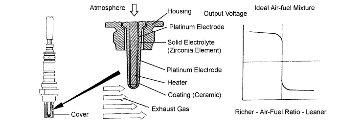
The heated oxygen sensor is used to monitor oxygen concentration in the exhaust gas. For optimum catalytic converter operation, the air-fuel mixture must be maintained near the ideal stoichiometric air-fuel ratio. The heated oxygen sensor output voltage changes suddenly in the vicinity of the stoichiometric air-fuel ratio. The ECM adjusts the fuel injection time so that the air-fuel ratio is nearly stoichiometric. The heated oxygen sensor generates a voltage between 0.1 and 0.9 V in response to oxygen concentration in the exhaust gas.If the oxygen concentration in the exhaust gas increases, the air-fuel ratio is called LEAN. The heated oxygen sensor voltage drops below 0.45 V and the heated oxygen sensor informs the ECM of the LEAN condition.If oxygen is not in the exhaust gas, the air-fuel ratio is called RICH. The heated oxygen sensor voltage increases above 0.45 V and the heated oxygen sensor informs the ECM of the RICH condition.- HINT:
- The ECM has a pulse width modulated control circuit to adjust current through the heater. The heated oxygen sensor heater circuit uses a relay on the +B side of the circuit.
DTC No.
| DTC Detection Condition
| Trouble Area
|
P0031
P0037
P0051
P0057
| Heated oxygen sensor heater current is below 0.25 A when heater operates with +B greater than 11.5 V
(1 trip detection logic)
| - Open or short in heated oxygen sensor heater circuit
- Heated oxygen sensor heater
- EFI MAIN relay
- ECM
|
P0032
P0038
P0052
P0058
| Heater current exceeds 2 A when heater operates
(1 trip detection logic)
| - Open or short in heated oxygen sensor heater circuit
- Heated oxygen sensor heater
- EFI MAIN relay
- ECM
|
MONITOR DESCRIPTION
The sensing portion of the heated oxygen sensor has a zirconia element which is used to detect the oxygen concentration in the exhaust. If the zirconia element is at the proper temperature and the difference of the oxygen concentration between the inside and outside surface of the sensor is large, the zirconia element will generate voltage signals. In order to increase the oxygen concentration detecting capacity in the zirconia element, the ECM supplements the heat from the exhaust with heat from a heating element inside the sensor. When the current in the heated oxygen sensor heater is out of the standard operating range, the ECM interprets this as a fault in the heated oxygen sensor heater. The ECM illuminates the MIL and sets a DTC.Normally, the heated oxygen sensor heater current is 0.4 to 1.0 A.Example:The ECM will set a high current DTC if the current in the sensor is more than 2 A. Similarly, the ECM will set a low current DTC if the current is less than 0.25 A.The monitor runs if the engine is started and run at idle for 9 minutes or more.
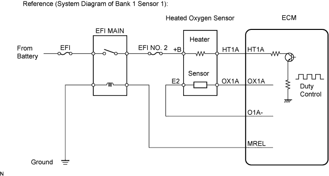
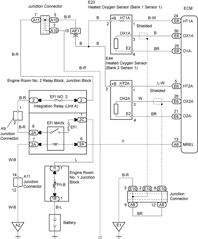
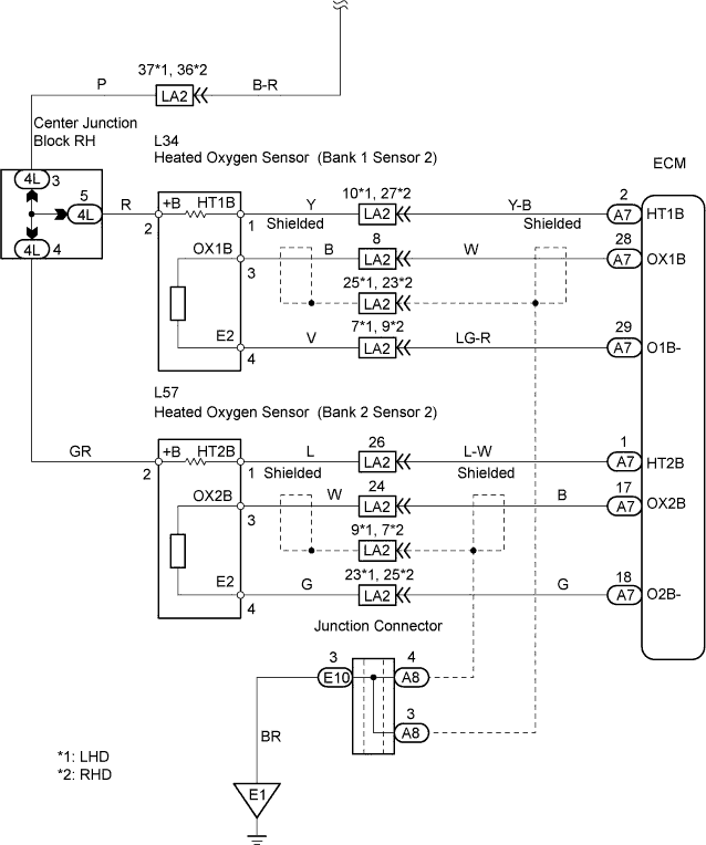
WIRING DIAGRAM
INSPECTION PROCEDURE
- HINT:
- Read freeze frame data using the intelligent tester. Freeze frame data records the engine conditions when a malfunction is detected. When troubleshooting, freeze frame data can help determine if the vehicle was running or stopped, if the engine was warmed up or not, if the air-fuel ratio was LEAN or RICH, and other data from the time the malfunction occurred.
- Bank 1 refers to the bank that includes cylinder No. 1.
- Bank 2 refers to the bank that does not include cylinder No. 1.
- Bank 1 includes cylinder No. 1, but bank 2 does not. Cylinder No. 1 is located in the front part of the engine, opposite the transmission.
- Sensor 1 refers to the sensor closest to the engine body.
- Sensor 2 refers to the sensor farthest away from the engine body.
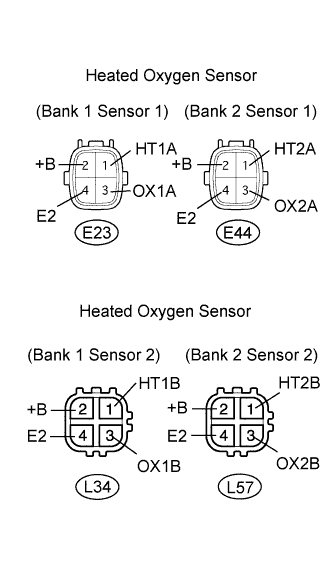
| 1.INSPECT HEATED OXYGEN SENSOR (HEATER RESISTANCE) |
Disconnect the E23, E44, L34 and L57 sensor connectors.
Measure the resistance of the sensor.
- Standard resistance: Sensor 1:
Tester Connection
| Specified Condition
|
1 (HT1A) - 2 (+B)
| 11 to 16 Ω
|
1 (HT2A) - 2 (+B)
| 11 to 16 Ω
|
1 (HT1A) - 4 (E2)
| 10 kΩ or higher
|
1 (HT2A) - 4 (E2)
| 10 kΩ or higher
|
- Standard resistance: Sensor 2:
Tester Connection
| Specified Condition
|
1 (HT1B) - 2 (+B)
| 11 to 16 Ω
|
1 (HT2B) - 2 (+B)
| 11 to 16 Ω
|
1 (HT1B) - 4 (E2)
| 10 kΩ or higher
|
1 (HT2B) - 4 (E2)
| 10 kΩ or higher
|
| | REPLACE HEATED OXYGEN SENSOR |
|
|
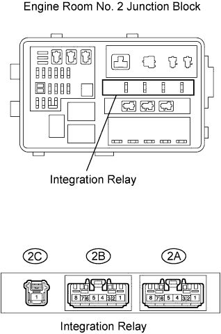
| 2.INSPECT INTEGRATION RELAY (EFI MAIN) |
Remove the integration relay from the engine room No. 2 junction block.
Measure the resistance of the EFI MAIN relay.
- Standard resistance:
Terminal Connections
| Specified Condition
|
2A-8 - 2C-1
| 10 kΩ or higher
|
2A-8 - 2C-1
| Below 1 Ω
(when battery voltage is applied to terminals 2A-6 and 2A-7)
|
| | REPLACE INTEGRATION RELAY |
|
|
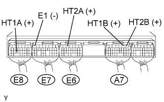
| 3.CHECK ECM (HT1A, HT2A, HT1B, HT2B VOLTAGE) |
Turn the engine switch on (IG).
Measure the voltage of the ECM.
- Standard voltage:
Tester Connection
| Specified Condition
|
E8-24 (HT1A) - E7-7 (E1)
| 9 to 14 V
|
E6-5 (HT2A) - E7-7 (E1)
| 9 to 14 V
|
A7-2 (HT1B) - E7-7 (E1)
| 9 to 14 V
|
A7-1 (HT2B) - E7-7 (E1)
| 9 to 14 V
|
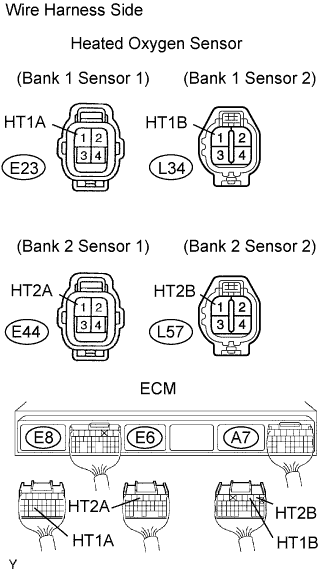
| 4.CHECK WIRE HARNESS (HEATED OXYGEN SENSOR - ECM) |
Disconnect the E23, E44, L34 and L57 sensor connectors.
Disconnect the A7, E6 and E8 ECM connectors.
Measure the resistance of the wire harness side connectors.
- Standard resistance:
Tester Connection
| Specified Condition
|
E23-1 (HT1A) - E8-24 (HT1A)
| Below 1 Ω
|
E44-1 (HT2A) - E6-5 (HT2A)
| Below 1 Ω
|
L34-1 (HT1B) - A7-2 (HT1B)
| Below 1 Ω
|
L57-1 (HT2B) - A7-1 (HT2B)
| Below 1 Ω
|
E23-1 (HT1A) or E8-24 (HT1A) - Body ground
| 10 kΩ or higher
|
E44-1 (HT2A) or E6-5 (HT2A) - Body ground
| 10 kΩ or higher
|
L34-1 (HT1B) or A7-2 (HT1B) - Body ground
| 10 kΩ or higher
|
L57-1 (HT2B) or A7-1 (HT2B) - Body ground
| 10 kΩ or higher
|
| | REPAIR OR REPLACE HARNESS AND CONNECTOR |
|
|
| 5.CHECK WIRE HARNESS (HEATED OXYGEN SENSOR - INTEGRATION RELAY) |
Disconnect the E23, E44, L34 and L57 sensor connectors.
Remove the integration relay from the engine room No. 2 junction block.
Measure the resistance of the wire harness side connectors.
- Standard resistance:
Tester Connection
| Specified Condition
|
E23-2 (+B) - 2A-8
| Below 1 Ω
|
E44-2 (+B) - 2A-8
| Below 1 Ω
|
L34-2 (+B) - 2A-8
| Below 1 Ω
|
L57-2 (+B) - 2A-8
| Below 1 Ω
|
E23-2 (+B) or 2A-8 - Body ground
| 10 kΩ or higher
|
E44-2 (+B) or 2A-8 - Body ground
| 10 kΩ or higher
|
L34-2 (+B) or 2A-8 - Body ground
| 10 kΩ or higher
|
L57-2 (+B) or 2A-8 - Body ground
| 10 kΩ or higher
|
| | REPAIR OR REPLACE HARNESS AND CONNECTOR |
|
|
| OK |
|
|
|
| CHECK ECM POWER SOURCE CIRCUIT |
|