Knock Sensor -- Installation |
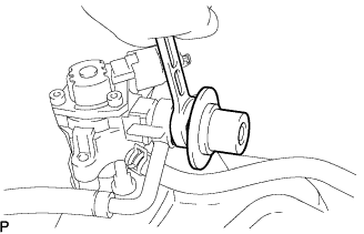
| 1. INSTALL KNOCK SENSOR |
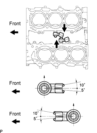 |
Install the 2 knock sensors so that they are horizontal as shown in the illustration. Then install the 2 bolts.
- Torque:
- 20 N*m{204 kgf*cm, 15 ft.*lbf}
- HINT:
- It is acceptable for the sensor to be titled +10° to -5°.
Connect the 2 sensor connectors.
| 2. INSTALL FUEL INJECTOR SEAL |
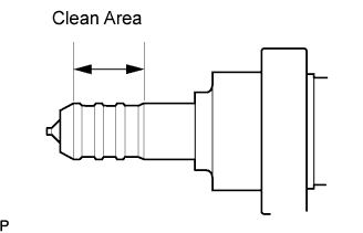
Apply engine conditioner to the injector area shown in the illustration. Using a cloth, clean carbon deposits from the injector and its grooves.
- NOTICE:
- Do not clean the tip of the injector.
- Do not use a wire brush to clean the injector.
- If an injector is dropped, replace it with a new one.
- Be extremely careful not to touch or strike the tips of the injectors.
 |
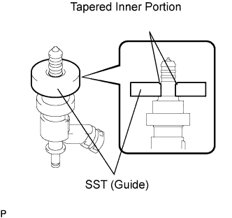
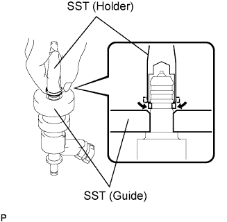
Apply engine oil to the injector contact surface of SST (guide). Then attach SST (guide) to the injector with the tapered inner portion facing the tip of the injector, as shown in the illustration.
- SST
- 09260-39015(09268-03020)
 |
Install a new injector seal to SST (holder).
- SST
- 09260-39015(09268-03010)
- NOTICE:
- Be careful not to install the injector seal to SST (holder) at an angle. Doing so will stretch the seal and correcting this problem is very complicated.
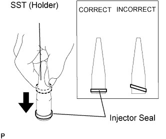 |
Install SST (holder with injector seal) to the tip of the injector. Using your fingers, slide the seal downward into the injector groove (injector connector side), as shown in the illustration.
- SST
- 09260-39015(09268-03010,09268-03020)
- HINT:
- Check that the seal covers the circumference of the injector groove as shown in the illustration.
 |
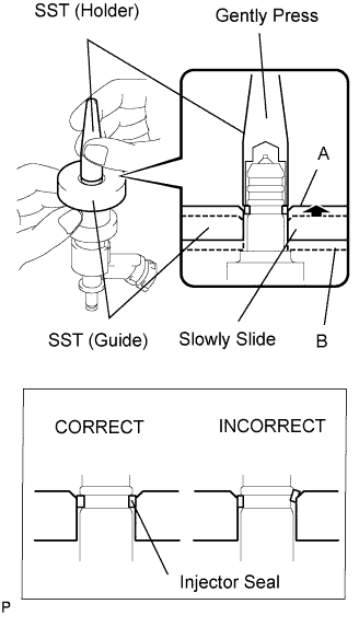
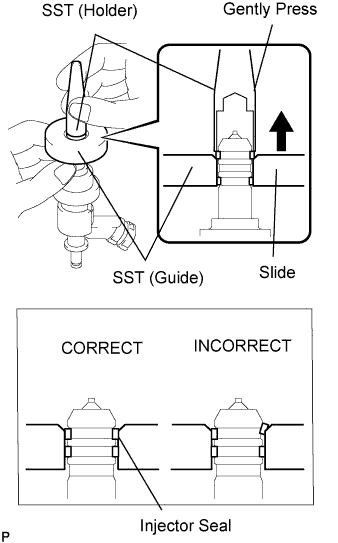
Using SST (holder), gently press downward on the injector seal (injector connector side). Then slowly slide SST (guide) towards the injector tip to settle the seal into the injector groove.
- SST
- 09260-39015(09268-03010,09268-03020)
- NOTICE:
- Be careful that the seal is not pinched between SST (guide) and the injector groove. Replace the seal if it becomes damaged.
- HINT:
- When using SST (guide) to settle the seal into the groove: SST (guide) only needs to be slid upward to the position labeled A in the illustration.
- After using SST (guide) to settle the seal into the groove: Return SST (guide) to its position labeled B in the illustration.
 |
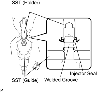
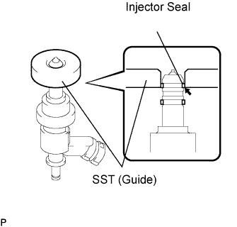
Install a new injector seal to the injector groove (injector tip side) as shown in the illustration.
- SST
- 09260-39015(09268-03010,09268-03020)
|
Check that the seal covers the circumference of the injector groove as shown in the illustration.
- SST
- 09260-39015(09268-03010,09268-03020)
- NOTICE:
- Make sure the seal does not slip into the welded groove of the injector shown in the illustration. If it does, replace it with a new one.
 |
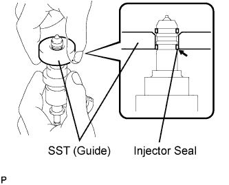
Slowly slide SST (guide) towards the tip of the injector. When the injector contact surface of SST (guide) aligns with the seal (injector connector side) as shown in the illustration, hold the position for 5 seconds or more to fully align the seal into the injector groove.
- SST
- 09260-39015(09268-03020)
- NOTICE:
- Be careful that the seal is not pinched between SST (guide) and the injector groove. Replace the seal if it becomes damaged.
- HINT:
- Set SST (guide) so that its bottom surface and seal are flush.
- If there is difficulty sliding SST upward, slowly wiggle it from side to side while sliding it up the injector little by little.
 |
Using SST (holder), gently press downward on the injector seal (injector tip side). Then slowly slide SST (guide) towards the injector tip to settle the seal into the injector groove.
- SST
- 09260-39015(09268-03010,09268-03020)
- NOTICE:
- Be careful that the seal is not pinched between SST (guide) and the injector groove. Replace the seal if it becomes damaged.
 |
Slowly slide SST (guide) towards the tip of the injector. When the injector contact surface of SST (guide) aligns with the seal (injector tip side) as shown in the illustration, hold the position for 5 seconds or more to fully align the seal into the injector groove.
- SST
- 09260-39015(09268-03020)
- NOTICE:
- Be careful that the seal is not pinched between SST (guide) and the injector groove. Replace the seal if it becomes damaged.
- HINT:
- Set SST (guide) so that its bottom surface and the seal's bottom surface are flush.
- If there is difficulty sliding SST upward, slowly wiggle it from side to side while sliding it up the injector little by little.
 |
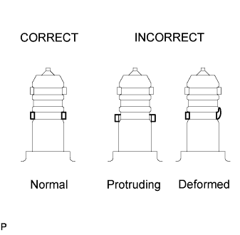
After installing the seals, check that the seal is not scratched, deformed or protruding from the injector groove.
- NOTICE:
- If scratched, deformed or protruding from the groove, replace it with a new one.
 |
| 3. INSTALL INJECTOR |
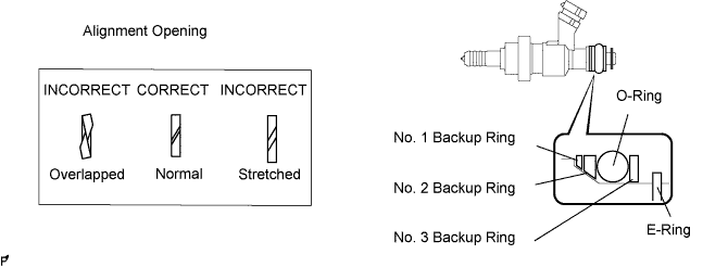
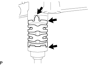
Install a new O-ring, new backup rings (No. 1, No. 2, No. 3) and new E-ring to the fuel injector as shown in the illustration.
- NOTICE:
- Check that there is no foreign matter or damaged areas in the injector's O-ring groove.
- Check that the installation direction of the No. 1 and No. 2 backup ring are correct.
- Make sure the backup rings and O-ring are installed in the correct order.
- Check that the alignment openings of the backup rings are not overlapped or stretched as shown in the illustration.
- After installing the O-ring, check that it is not contaminated with foreign matter and is not damaged.
Install the injector nozzle holder clamp.
Apply gasoline to the O-ring. Install the nozzle holder clamp by aligning the protruding part of the clamp to the notch of the delivery pipe.
- NOTICE:
- Make sure there is no gap between the delivery pipe and clamp.
- Check that there is no foreign matter or damage in the injector insertion hole of the delivery pipe.
- Insert the injector straight into the delivery pipe without tilting it.
 |
| 4. INSTALL NO. 1 FUEL DELIVERY PIPE |
Install a new injector vibration insulator to the cylinder head.
Apply lubricant to the installation hole of the injector.
Insert the stud bolt into the fuel delivery pipe until the screw threads protrude enough so that a nut can be attached.
- NOTICE:
- If an injector is dropped, replace it with a new one.
- Check that there is no foreign matter or damage in the injector insertion hole of the delivery pipe.
- Be extremely careful not to touch or strike the tips of the injectors.
- When inserting the fuel delivery pipe, push it in evenly without tilting it.
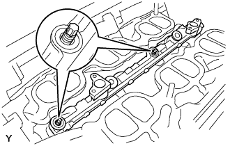 |
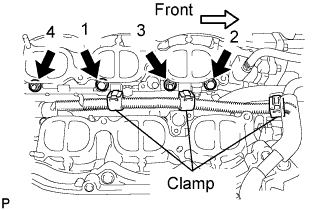
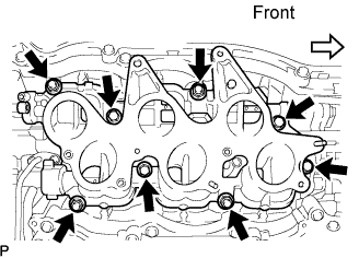
Install the fuel delivery pipe by uniformly tightening the 2 bolts and 2 nuts in several passes in the order shown in the illustration.
- Torque:
- 21 N*m{214 kgf*cm, 15 ft.*lbf}
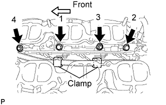 |
Connect the 3 connectors and 2 clamps.
| 5. INSTALL NO. 2 FUEL DELIVERY PIPE |
Install a new injector vibration insulator to the cylinder head.
Apply lubricant to the installation hole of the injector.
Insert the stud bolt into the No. 2 fuel delivery pipe until the screw threads protrude enough so that a nut can be attached.
- NOTICE:
- If an injector is dropped, replace it with a new one.
- Check that there is no foreign matter or damage in the injector insertion hole of the delivery pipe.
- Be extremely careful not to touch or strike the tips of the injectors.
- When inserting the fuel delivery pipe, push it in evenly without tilting it.
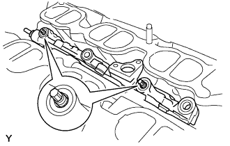 |
Install the fuel delivery pipe by uniformly tightening the 2 bolts and 2 nuts in several passes in the order shown in the illustration.
- Torque:
- 21 N*m{214 kgf*cm, 15 ft.*lbf}
 |
Connect the 3 connectors and 3 clamps.
| 6. INSTALL NO. 3 FUEL PIPE |
Install a new O-ring, new backup rings (No. 1, No. 2) and new E-ring to the fuel injector as shown in the illustration.

- NOTICE:
- Check that there is no foreign matter or damaged areas in the injector's O-ring groove.
- Check that the installation directions of the No. 1 and No. 2 backup ring are correct.
- Make sure the backup rings and O-ring are installed in the correct order.
- Check that the alignment openings of the backup rings are not overlapped or stretched as shown in the illustration.
- After installing the O-ring, check that it is not contaminated with foreign matter and is not damaged.
- Check that the fuel pipe installation end is not contaminated with foreign matter and is not damaged.
Apply gasoline to the O-ring.
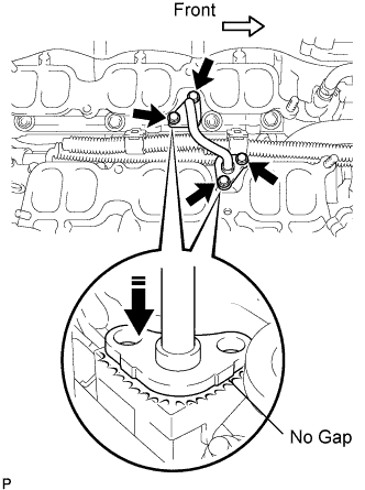 |
Using your hand, press the fuel pipe and delivery pipe together until there is no gap between them. Then install the No. 3 fuel pipe with the 4 bolts.
- Torque:
- 10 N*m{102 kgf*cm, 7 ft.*lbf}
| 7. CONNECT NO. 2 FUEL PIPE |
Install a new O-ring, new backup rings (No. 1 and No. 2) and new E-ring to the fuel injector as shown in the illustration.
- NOTICE:
- Check that there is no foreign matter or damaged areas in the injector's O-ring groove.
- Check that the installation directions of the No. 1 and No. 2 backup rings are correct.
- Make sure the backup rings and O-ring are installed in the correct order.
- Check that the alignment openings of the backup rings are not overlapped or stretched as shown in the illustration.
- After installing the O-ring, check that it is not contaminated with foreign matter and is not damaged.
- Check that the No. 3 fuel pipe installation end is not contaminated with foreign matter and is not damaged.
Apply gasoline to the O-ring and connect the fuel pipe to the delivery pipe.
- NOTICE:
- Do not install the bolt at this time.
| 8. INSTALL HIGH PRESSURE SIDE FUEL PUMP |
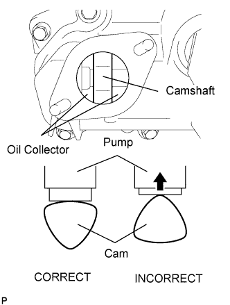
Turn the crankshaft until the flat of the cam is facing the cylinder head cover's fuel pump attachment hole, as shown in the illustration.
- HINT:
- When installing the fuel pump using the procedure described above: By not using the crankshaft pointed side to push up the pump activation surface, it is easier to install the fuel pump and No. 2 fuel pipe later.
 |
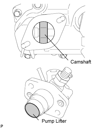
Pour 30 cc of engine oil through the cylinder head cover's fuel pump attachment hole into the cylinder head oil collector.
Apply a coat of engine oil to the pump activation cam and pump lifter part.
 |
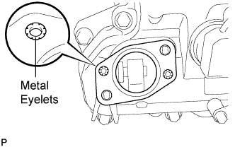
Install a new fuel pump insulator to the cylinder head cover. Then pass the 2 stud bolts through the holes of the fuel pump and set it on the insulator.
- NOTICE:
- Install the insulator so that the open sides of the metal eyelets are facing outward, as shown in the illustration.
 |
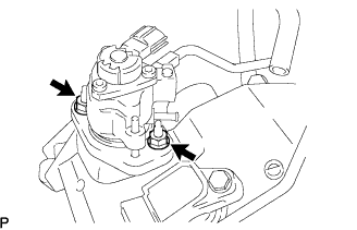
Install the union nut of the No. 1 fuel pipe without damaging its seal surface. Tighten the nut as much as possible by hand.
Install the 2 nuts and tighten them in several passes.
- Torque:
- 25 N*m{255 kgf*cm, 18 ft.*lbf}
 |
Connect the fuel hose.
| 9. INSTALL NO. 2 FUEL PIPE |
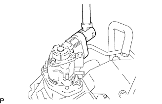
Using a 19 mm union nut wrench, connect the fuel pipe.
- Torque:
- 30 N*m{306 kgf*cm, 22 ft.*lbf}
 |
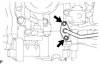
Install the No. 2 fuel pipe to the delivery pipe with the 2 bolts.
- Torque:
- 10 N*m{102 kgf*cm, 7 ft.*lbf}
 |
Connect the connector to the fuel pump.
| 10. INSTALL NO. 1 FUEL PIPE |
|
Install the fuel pipe to the delivery pipe with the 2 bolts.
- Torque:
- 10 N*m{102 kgf*cm, 7 ft.*lbf}
| 11. INSTALL FUEL PRESSURE PULSATION DAMPER |
 |
Install 2 new gaskets, the fuel main tube and pulsation damper to the fuel pump.
- Torque:
- 40 N*m{408 kgf*cm, 28 ft.*lbf}
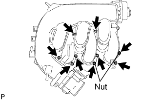
| 12. INSTALL INTAKE MANIFOLD |
Install a new gasket and the intake manifold with the 4 bolts and 4 nuts.
- Torque:
- 21 N*m{214 kgf*cm, 15 ft.*lbf}
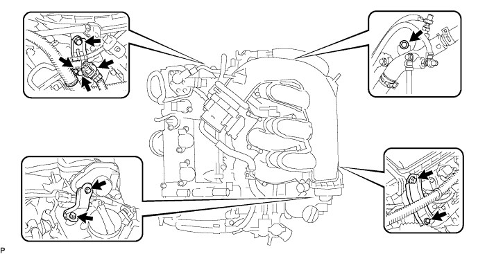
 |
Connect the DC motor connector for the SCV.
Connect the SCV position sensor connector.
| 13. INSTALL INTAKE AIR SURGE TANK |
Install a new gasket to the intake air surge tank.
 |
Install the intake air surge tank with the 2 nuts.
- Torque:
- 18 N*m{184 kgf*cm, 13 ft.*lbf}
Using a 5 mm hexagon socket wrench, install the 7 bolts.
- Torque:
- 16 N*m{163 kgf*cm, 12 ft.*lbf}
Install the 2 surge tank stays with the 4 bolts.
- Torque:
- 21 N*m{214 kgf*cm, 15 ft.*lbf}
Connect the 2 wire harness clamps.
Connect the water hose joint with the bolt.
- Torque:
- 10 N*m{102 kgf*cm, 7 ft.*lbf}
Install the intake manifold stay with the 2 bolts.
- Torque:
- 10 N*m{102 kgf*cm, 7 ft.*lbf}
Connect the wire harness clamp to the intake air surge tank.
Connect the IACV connector.
Connect the SCV position sensor connector.
Connect the throttle motor connector.
| 14. CONNECT FUEL MAIN TUBE |
 |
- NOTICE:
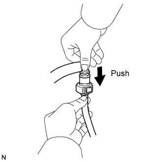
- Before installing the fuel main tube's connector to the fuel main pipe, check the connector for damage and foreign matter.
Connect the connector to the fuel main pipe. Push the two parts together firmly until a "click" sound is heard. Then attach the lock claws to the connector by pushing down on the connector cover.
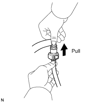
Check that the connector and fuel main pipe are securely connected by trying to pull them apart.
 |
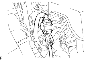
Install the fuel pipe clamp.
 |
| 15. CONNECT VENTILATION HOSE |
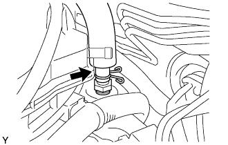 |
Connect the ventilation hose to the ventilation valve.
| 16. INSTALL ENGINE REAR COVER |
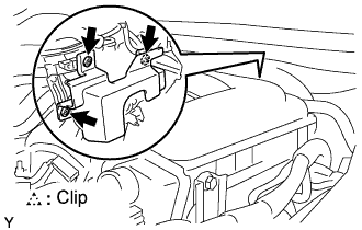 |
Install the engine rear cover with the 3 clips.
| 17. CONNECT UNION TO CHECK VALVE HOSE |
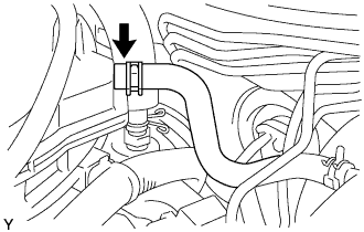 |
Connect the hose to the surge tank.
| 18. CONNECT HEATER WATER INLET HOSE |
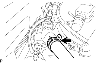 |
Connect the hose to the pipe.
| 19. CONNECT WATER BY-PASS HOSE |
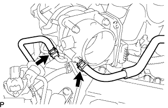 |
Connect the 2 water by-pass hoses to the throttle body.
| 20. INSTALL AIR CLEANER CAP WITH AIR CLEANER HOSE |
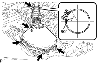 |
Install the air cleaner cap with air cleaner hose assembly with the 4 clamps and hose clamp.
- HINT:
- Be sure to install the air cleaner assembly so that the screw part of the hose clamp is as shown in the illustration.
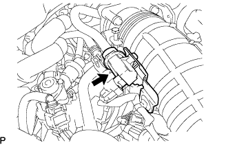
Install the VSV (for EVAP )to the air cleaner hose.
 |
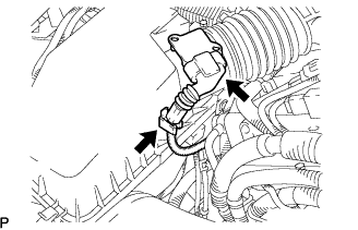
Connect the MAF meter connector and clamp to the air cleaner.
 |
| 21. CONNECT NO. 2 VENTILATION HOSE |
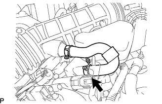 |
Connect the ventilation hose to the cylinder head cover with the clamp.
| 22. CONNECT CABLE TO NEGATIVE BATTERY TERMINAL |
| 23. ADD ENGINE COOLANT |
- NOTICE:
- Before adding engine coolant, turn the A/C switch OFF.
Tighten all the plugs and fill the radiator with TOYOTA Super Long Life Coolant (SLLC).
- Torque:
- 12.7 N*m{130 kgf*cm, 9 ft.*lbf} for cylinder block drain cock plug
Add engine coolant.
- Specified capacity:
- 9.1 liters (9.6 US qts, 8.0 lmp. qts)
- NOTICE:
- When pressing the radiator hose:
- Wear protective gloves.
- Be careful as the radiator hose is hot.
- Keep your hands away from the radiator fan.
- HINT:
- TOYOTA vehicles are filled with TOYOTA SLLC at the factory. In order to avoid damage to the engine cooling system and other technical problems, only use TOYOTA SLLC or similar high quality ethylene glycol based non-silicate, non-amine, non-nitrite, non-borate coolant with long-life hybrid organic acid technology (coolant with long-life hybrid organic acid technology consists of a combination of low phosphates and organic acids).
- Please contact your TOYOTA dealer for further details.
- The thermostat open timing can be confirmed by pressing the inlet radiator hose by hand, and checking when the engine coolant starts to flow inside the hose.
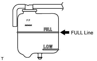
Slowly pour coolant into the radiator reservoir until it reaches the FULL line.
Press the inlet and outlet radiator hoses several times by hand, and then check the level of the coolant.
If the coolant level is low, add coolant.
Install the radiator cap and reservoir cap.
Bleed air from the cooling system.
- NOTICE:
- Before starting the engine to warm up the engine, turn the A/C switch OFF.
Warm up the engine until the thermostat opens. While the thermostat is open, circulate the coolant for several minutes.
- HINT:
- The thermostat open timing can be confirmed by pressing the inlet radiator hose by hand, and checking when the engine coolant starts to flow inside the hose.
- NOTICE:
- When pressing the radiator hoses:
- Wear protective gloves.
- Be careful as the radiator hoses are hot.
- Keep your hands away from the radiator fan.
Maintain the engine speed at 2,000 to 2,500 rpm.
Press the inlet and outlet radiator hoses several times by hand to bleed air.
- NOTICE:
- When pressing the radiator hoses:
- Wear protective gloves.
- Be careful as the radiator hoses are hot.
- Keep your hands away from the radiator fan.
Stop the engine, and wait until the engine coolant cools down to ambient temperature.
- CAUTION:
- Do not remove the radiator cap while the engine and radiator are still hot. Pressurized, hot engine coolant and steam may be released and cause serious burns.
Check the coolant level in the radiator reservoir.
If the coolant level is low, add SLLC to the radiator reservoir FULL line.
 |
| 24. CHECK FOR ENGINE COOLANT LEAKAGE |
 |
- CAUTION:
- Do not remove the radiator cap while the engine and radiator are still hot. Pressurized, hot engine coolant and steam may be released and cause serious burns.
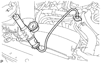
Fill the radiator with coolant and attach a radiator cap tester.
Warm up the engine.
Using a radiator cap tester, increase the pressure inside the radiator to 118 kPa (1.2 kgf/cm, 17 psi), and check that the pressure does not drop.
If the pressure drops, check the hoses, radiator and water pump for leaks. If no external leaks are found, check the heater core, cylinder block and head.
| 25. CHECK FOR FUEL LEAKAGE |
Start the engine, and check that there are no fuel leaks after performing maintenance anywhere on the system.
| 26. CHECK FOR ENGINE OIL LEAKS |
Start the engine, and check that there are no oil leaks after performing maintenance.
| 27. INSTALL V-BANK COVER |
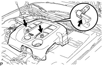 |
Install the V-bank cover with the 2 nuts.
- Torque:
- 5.0 N*m{51 kgf*cm, 44 in.*lbf}
| 28. INSTALL ENGINE ROOM SIDE COVER RH |
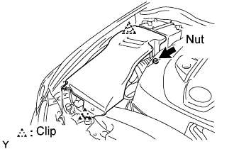 |
Install the side cover with the 2 clips and nut.
| 29. REMOVE COOL AIR INTAKE DUCT SEAL |
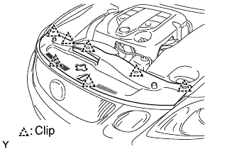 |
Install the intake duct seal with the 7 clips.
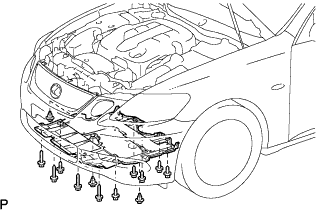
| 30. REMOVE ENGINE UNDER COVER |
Install the under cover with the 10 bolts and 3 clips.
 |
| 31. PERFORM INITIALIZATION |
Perform initialization (Click here).
- NOTICE:
- Certain systems need to be initialized after disconnecting and reconnecting the cable from the negative (-) battery terminal.
| 32. WARM UP ENGINE |
After the engine is warmed up, check that the maintained parts operate normally.