Engine. Lexus Gs430, Gs300. Uzs190 Grs190
3Gr-Fse Engine Control System. Lexus Gs430, Gs300. Uzs190 Grs190
READ VALUE USING INTELLIGENT TESTER (STARTER SIGNAL)
INSPECT PARK / NEUTRAL POSITION SWITCH
DTC P0617 Starter Relay Circuit High |
DESCRIPTION
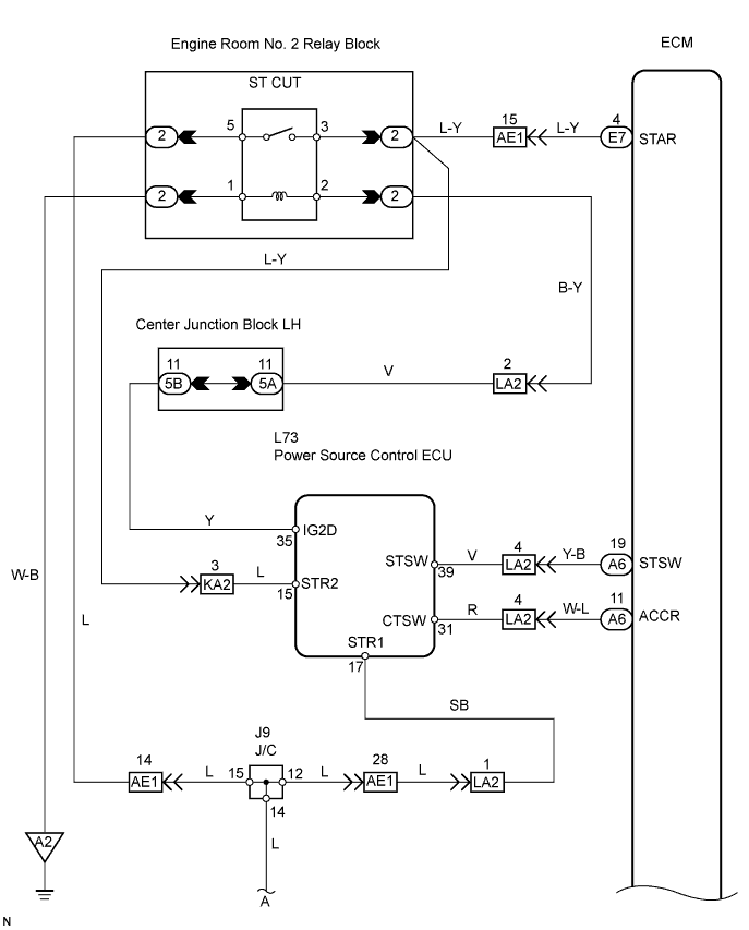
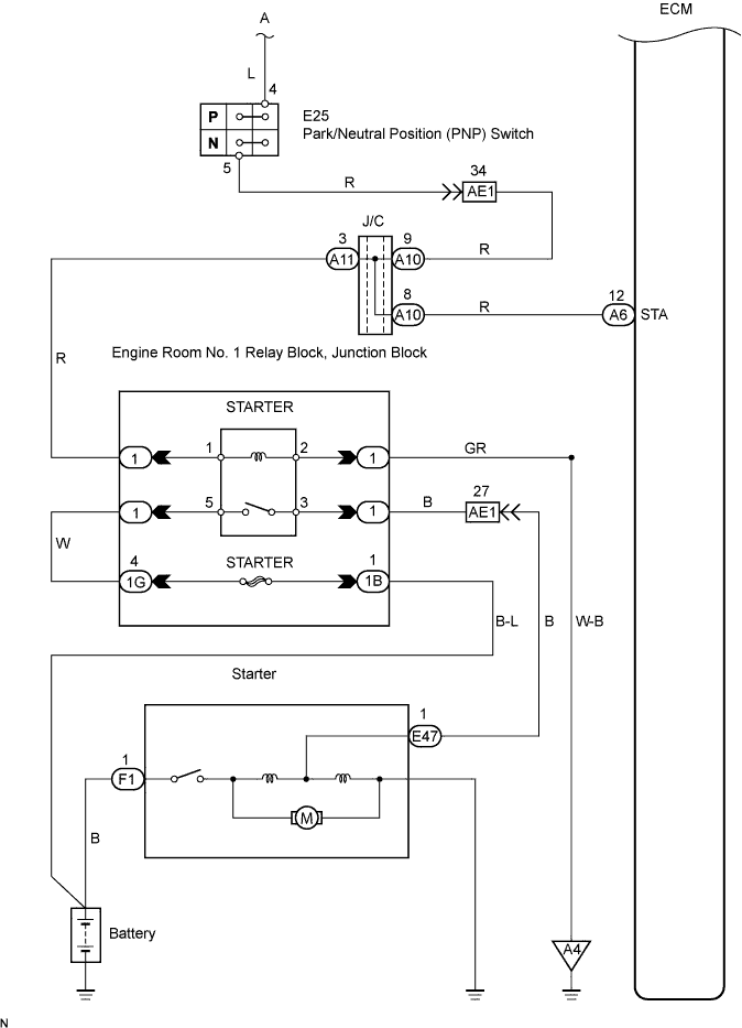
While the engine is being cranked, the positive battery voltage is applied to terminal STA of the ECM.If the ECM detects the Starter Control (STA) signal while the vehicle is being driven, it determines that that there is a malfunction in the STA circuit. The ECM then illuminates the MIL and sets the DTC.
This monitor runs when the vehicle is driven at 20 km/h (12.4 mph) for over 20 seconds.
| DTC No. | DTC Detection Condition | Trouble Area |
| P0617 | When conditions (a), (b) and (c) met, positive (+B) battery voltage 10.5 V or more applied to ECM for 20 seconds (1 trip detection logic): (a) Vehicle speed more than 20 km/h (12.4 mph) (b) Engine speed more than 1,000 rpm (c) STA signal ON |
|
WIRING DIAGRAM
INSPECTION PROCEDURE
- HINT:
- The following troubleshooting flowchart is based on the premise that the engine is cranked normally. If the engine will not crank, proceed to the problem symptoms table on page Click here.
- Read freeze frame data using the intelligent tester. Freeze frame data records the engine conditions when a malfunction is detected. When troubleshooting, freeze frame data can help determine if the vehicle was running or stopped, if the engine was warmed up or not, if the air-fuel ratio was lean or rich, and other data from the time the malfunction occurred.
| 1.READ VALUE USING INTELLIGENT TESTER (STARTER SIGNAL) |
Connect the intelligent tester to the DLC3.
Turn the engine switch on (IG) and turn the tester ON.
Enter the following menus: Power train / Engine / Data List / Starter Signal.
Check the value displayed on the tester when the engine switch is turned to the ON and START positions.
- OK:
Engine Switch Condition ON START Starter Signal OFF ON
|
| ||||
| NG | |
| 2.INSPECT PARK / NEUTRAL POSITION SWITCH |
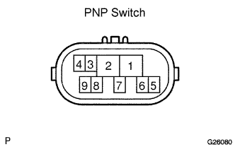 |
Inspect the Park/Neutral Position (PNP) switch.
Disconnect the E25 PNP switch connector.
Measure the resistance when the transmission gear selector lever is moved to each position.
- Standard resistance:
Gear Selector Lever Position Tester Connection Specified Condition P 4 - 5 Below 1 Ω N 4 - 5 Below 1 Ω
Reconnect the PNP switch connector.
|
| ||||
| OK | ||
| ||