READ VALUE USING INTELLIGENT TESTER (INTAKE AIR TEMPERATURE)
READ VALUE USING INTELLIGENT TESTER (CHECK FOR OPEN IN WIRE HARNESS)
READ VALUE USING INTELLIGENT TESTER (CHECK FOR OPEN IN ECM)
READ VALUE USING INTELLIGENT TESTER (CHECK FOR SHORT IN WIRE HARNESS)
READ VALUE USING INTELLIGENT TESTER (CHECK FOR SHORT IN ECM)
DTC P0110 Intake Air Temperature Circuit Malfunction |
DTC P0112 Intake Air Temperature Circuit Low Input |
DTC P0113 Intake Air Temperature Circuit High Input |
DESCRIPTION
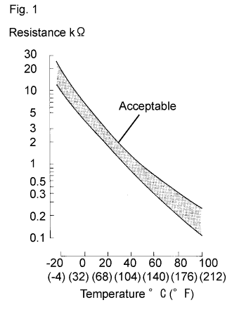
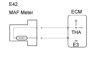
- The Intake Air Temperature (IAT) sensor, mounted on the Mass Air Flow (MAF) meter, monitors the IAT. The IAT sensor has a built in thermistor with a resistance that varies according to the temperature of the intake air. When the IAT is low, the resistance of the thermistor increases. When the temperature is high, the resistance drops. These variations in resistance are transmitted to the ECM as voltage changes (See Fig. 1).
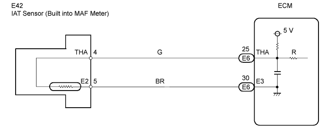
- The IAT sensor is powered by a 5 V supply from the THA terminal of the ECM, via resistor R.
- Resistor R and the IAT sensor are connected in series. When the resistance value of the IAT sensor changes, according to changes in the IAT, the voltage at terminal THA also varies. Based on this signal, the ECM increases the fuel injection volume when the engine is cold to improve drivability.
- HINT:
- When any of DTCs P0110, P0112 and P0113 are set, the ECM enters fail-safe mode. During fail-safe mode, the IAT is estimated to be 20°C (68°F) by the ECM. Fail-safe mode continues until a pass condition is detected.
| DTC No. | Proceed to | DTC Detection Condition | Trouble Area |
| P0110 | Step 1 | Open or short in Intake Air Temperature (IAT) sensor circuit for 0.5 seconds (1 trip detection logic) |
|
| P0112 | Step 4 | Short in Intake Air Temperature (IAT) sensor circuit for 0.5 seconds (1 trip detection logic) |
|
| P0113 | Step 2 | Open in Intake Air Temperature (IAT) sensor circuit for 0.5 seconds (1 trip detection logic) |
|
- HINT:
- When any of these DTCs are set, check the IAT by entering the following menus on the intelligent tester: Powertrain / Engine / Data List / Intake Air.
| Temperature Displayed | Malfunction |
| -40°C (-40°F) | Open circuit |
| 140°C (284°F) or higher | Short circuit |
MONITOR DESCRIPTION
The ECM monitors the sensor voltage and uses this value to calculate the Intake Air Temperature (IAT). When the sensor output voltage deviates from the normal operating range, the ECM interprets this as a malfunction in the IAT sensor and sets a DTC.Example:
If the sensor output voltage is -40°C (-40°F) for 0.5 seconds or more, the ECM determines that there is an open in the IAT sensor circuit, and sets DTC P0113. Conversely, if the output voltage is more than 140°C (284°F) for 0.5 seconds or more, the ECM determines that there is a short in the sensor circuit, and sets DTC P0112.
If the malfunction is not repaired successfully, a DTC is set 0.5 seconds after the engine is next started.
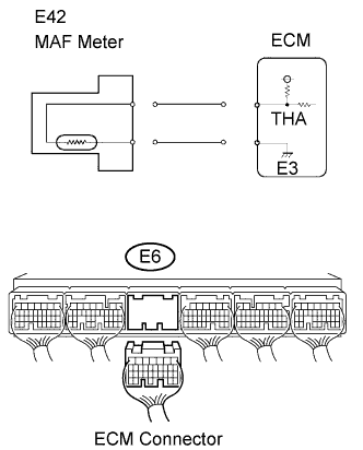
WIRING DIAGRAM
INSPECTION PROCEDURE
- HINT:
- If other DTCs relating to different systems that have terminal E3 as the ground terminal are output simultaneously, terminal E3 may have an open circuit.
- Read freeze frame data using the intelligent tester. Freeze frame data records the engine conditions when malfunctions are detected. When troubleshooting, freeze frame data can help determine if the vehicle was moving or stationary, if the engine was warmed up or not, if the air-fuel ratio was lean or rich, and other data from the time the malfunction occurred.
| 1.READ VALUE USING INTELLIGENT TESTER (INTAKE AIR TEMPERATURE) |
Connect the intelligent tester to the DLC3.
Turn the engine switch on (IG).
Turn the tester ON.
Enter the following menus: Powertrain / Engine / Data List / Intake Air.
Read the value displayed on the tester.
- Standard:
- Same as actual Intake Air Temperature (IAT).
- Result:
Temperature Displayed Proceed to -40 °C (-40°F) A 140°C (284°F) or higher B Same as actual IAT C
- HINT:
- If there is an open circuit, the intelligent tester indicates -40°C (-40°F).
- If there is a short circuit, the intelligent tester indicates 140°C (284°F) or higher.
|
| ||||
|
| ||||
| A | |
| 2.READ VALUE USING INTELLIGENT TESTER (CHECK FOR OPEN IN WIRE HARNESS) |
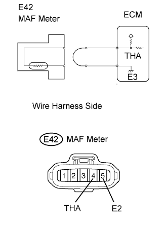 |
Disconnect the E42 MAF meter connector.
Connect terminals THA and E2 of the MAF meter wire harness side connector.
Connect the intelligent tester to the DLC3.
Turn the engine switch on (IG).
Turn the tester ON.
Enter the following menus: Powertrain / Engine / Data List / Intake Air.
Read the value displayed on the tester.
- Standard:
- 140°C (284°F) or higher
Reconnect the MAF meter connector.
|
| ||||
| NG | |
| 3.READ VALUE USING INTELLIGENT TESTER (CHECK FOR OPEN IN ECM) |
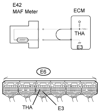 |
Disconnect the E42 MAF meter connector.
Connect terminals THA and E3 of the E6 ECM connector.
- HINT:
- Before checking, do visual and contact pressure checks on the ECM connector.
Connect the intelligent tester to the DLC3.
Turn the engine switch on (IG).
Turn the tester ON.
Enter the following menus: Powertrain / Engine / Data List / Intake Air.
Read the value displayed on the tester.
- Standard:
- 140°C (284°F) or higher
Reconnect the MAF meter connector.
|
| ||||
| NG | ||
| ||
| 4.READ VALUE USING INTELLIGENT TESTER (CHECK FOR SHORT IN WIRE HARNESS) |
 |
Disconnect the E42 MAF meter connector.
Connect the intelligent tester to the DLC3.
Turn the engine switch on (IG).
Turn the tester ON.
Enter the following menus: Powertrain / Engine / Data List / Intake Air.
Read the value displayed on the tester.
- Standard:
- -40°C (-40°F) or higher
Reconnect the MAF meter connector.
|
| ||||
| NG | |
| 5.READ VALUE USING INTELLIGENT TESTER (CHECK FOR SHORT IN ECM) |
 |
Disconnect the E42 MAF meter connector.
Disconnect the E6 ECM connector.
Connect the intelligent tester to the DLC3.
Turn the engine switch on (IG).
Turn the tester ON.
Enter the following menus: Powertrain / Engine / Data List / Intake Air.
Read the value displayed on the tester.
- Standard:
- -40°C (-40°F) or higher
Reconnect the connectors.
|
| ||||
| NG | ||
| ||