CHECK ANY OTHER DTCS OUTPUT (IN ADDITION TO DTC P0014, P0015, P0024 OR P0025)
PERFORM ACTIVE TEST BY USING INTELLIGENT TESTER (OPERATE OCV)
CHECK WHETHER DTC OUTPUT RECURS (DTC P0014, P0015, P0024 OR P0025)
CHECK VALVE TIMING (CHECK FOR LOOSE AND JUMPED TEETH ON TIMING CHAIN)
INSPECT CAMSHAFT TIMING OIL CONTROL VALVE ASSEMBLY (OCV FOR EXHAUST CAMSHAFT)
INSPECT OIL CONTROL VALVE FILTER
REPLACE CAMSHAFT TIMING GEAR ASSEMBLY (FOR EXHAUST CAMSHAFT)
READ OUTPUT DTC (CHECK IF DTC OUTPUT RECURS)
DTC P0014 Camshaft Position "B" - Timing Over-Advanced or System Performance (Bank 1) |
DTC P0015 Camshaft Position "B" - Timing Over-Retarded (Bank 1) |
DTC P0024 Camshaft Position "B" - Timing Over-Advanced or System Performance (Bank 2) |
DTC P0025 Camshaft Position "B" - Timing Over-Retarded (Bank 2) |
DESCRIPTION
- HINT:
- If DTC P0014, P0015, P0024 or P0025 is present, check the VVT (Variable Valve Timing) system.
| DTC No. | DTC Detection Condition | Trouble Area |
| P0014 P0024 | Advanced cam timing: With warm engine and engine speed of between 500 rpm and 4,000 rpm, all conditions (a), (b) and (c) met (1 trip detection logic): (a) Difference between target and actual exhaust valve timing more than 5 °CA (Crankshaft Angle) for 4.5 seconds (b) Current exhaust valve timing fixed (timing changes less than 5°CA in 5 seconds) (c) Variations in VVT controller timing more than 19°CA of maximum delayed timing (advanced) |
|
| P0015 P0025 | Retarded cam timing: With warm engine and engine speed of between 500 rpm and 4,000 rpm, all conditions (a), (b) and (c) met (2 trip detection logic): (a) Difference between target and actual exhaust valve timing more than 5°CA (Crankshaft Angle) for 4.5 seconds (b) Current exhaust valve timing fixed (timing changes less than 5°CA in 5 seconds) (c) Variations in VVT controller timing more than 19°CA or less of maximum delayed timing (retarded) |
|
MONITOR DESCRIPTION
The ECM optimizes the exhaust valve timing using the VVT (Variable Valve Timing) system to control the exhaust camshaft. The VVT system includes the ECM, the oil Control Valve (OCV) and the VVT controller. The ECM sends a target duty-cycle control signal to the OCV. This control signal regulates the oil pressure supplied to the VVT controller. The VVT controller can advance or retard the exhaust camshaft.If the difference between the target and actual exhaust valve timing is large, and changes in actual exhaust valve timing are small, the ECM interprets this as the VVT controller stuck malfunction and sets a DTC.
Example:
A DTC is set when the following conditions 1), 2) and 3) are met:
1) The difference between the target and actual exhaust valve timing is more than 5°CA (Crankshaft Angle) and the condition continues for more than 4.5 seconds.
2) It takes 5 seconds or more to change the valve timing by 5°CA.
3) After above conditions 1) and 2) are met, the OCV is forcibly activated 63 times or more.
DTCs P0014 and P0024 (Advanced Cam Timing) are subject to 1 trip detection logic.
DTCs P0015 and P0025 (Retarded Cam Timing) are subject to 2 trip detection logic.
These DTCs indicate that the VVT controller cannot operate properly due to OCV malfunctions or the presence of foreign objects in the OCV.
The monitor will not run unless the following conditions are met:
- The engine is warm (the engine coolant temperature is 75°C [167°F] or more).
- The vehicle has been driven at more than 64 km/h (40 mph) for 3 minutes.
- The engine has idled for 3 minutes.
WIRING DIAGRAM
Refer to DTC P0010 on page Click here.INSPECTION PROCEDURE
- HINT:
| Abnormal bank | Advanced timing over (Valve timing is out of specified range) | Retarded timing over (Valve timing is out of specified range) |
| Bank 1 | P0014 | P0015 |
| Bank 2 | P0024 | P0025 |
- If DTC P0014 or P0015 is displayed, check the bank 1 VVT system for exhaust camshaft circuit.
- Bank 1 refers to the bank that includes cylinder No. 1.
- If DTC P0024 or P0025 is displayed, check the bank 2 VVT system for exhaust camshaft circuit.
- Bank 2 refers to the bank that does not include cylinder No. 1.
- Read freeze frame data using the intelligent tester. Freeze frame data records the engine conditions when malfunctions are detected. When troubleshooting, freeze frame data can help determine if the vehicle was moving or stationary, if the engine was warmed up or not, if the air-fuel ratio was lean or rich, and other data from the time the malfunction occurred.
| 1.CHECK ANY OTHER DTCS OUTPUT (IN ADDITION TO DTC P0014, P0015, P0024 OR P0025) |
Connect the intelligent tester to the DLC3.
Turn the engine switch on (IG) and turn the tester ON.
Enter the following menus: Powertrain / Engine / DTC.
Read DTCs.
Result: Display (DTC output) Proceed to P0014, P0015, P0024 or P0025 A P0014, P0015, P0024 or P0025 and other DTCs B - HINT:
- If any DTCs other than P0014, P0015, P0024 or P0025 are output, troubleshoot those DTCs first.
|
| ||||
| A | |
| 2.PERFORM ACTIVE TEST BY USING INTELLIGENT TESTER (OPERATE OCV) |
Connect the intelligent tester to the DLC3.
Start the engine and turn the tester ON.
Warm up the engine.
On the tester, enter the following menus: Powertrain / Engine / Active Test / Control the VVT Ehaust Linear (Bank 1) or Control the VVT Exhaust Linear (Bank 2).
Check the engine speed while operating the Oil Control Valve (OCV) using the tester.
OK: Tester Operation Specified Condition OCV OFF Normal engine speed OCV ON Engine idles roughly or stalls (soon after OCV switched from OFF to ON)
|
| ||||
| OK | |
| 3.CHECK WHETHER DTC OUTPUT RECURS (DTC P0014, P0015, P0024 OR P0025) |
Connect the intelligent tester to the DLC3.
Turn the engine switch on (IG) and turn the tester ON.
Clear DTCs (Click here).
Start the engine and warm it up.
Switch the ECM from normal mode to check mode using the tester (Click here).
Drive the vehicle for more than 10 minutes.
Read DTCs using the tester.
- OK:
- No DTC output.
|
| ||||
| OK | ||
| ||
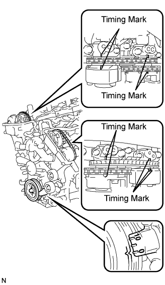
| 4.CHECK VALVE TIMING (CHECK FOR LOOSE AND JUMPED TEETH ON TIMING CHAIN) |
 |
Remove the cylinder head cover RH and LH.
Turn the crankshaft pulley, and align its groove with the timing mark "0" of the timing chain cover.
Check that the timing marks of the camshaft timing gears are aligned with the timing marks of the bearing cap as shown in the illustration.
If not, turn the crankshaft 1 revolution (360°), then align the marks as above.- OK:
- Timing marks on crankshaft timing gears are aligned as shown in the illustration.
Reinstall the cylinder head cover.
|
| ||||
| OK | |
| 5.INSPECT CAMSHAFT TIMING OIL CONTROL VALVE ASSEMBLY (OCV FOR EXHAUST CAMSHAFT) |
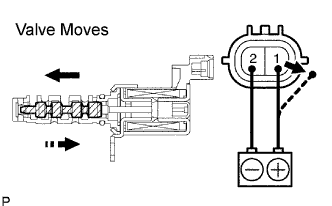 |
Remove the OCV.
Measure the resistance between the terminals of the OCV.
- Standard:
- 6.9 to 7.9 Ω at 20°C (68°F)
Apply the positive battery voltage to terminal 1 and negative battery voltage to terminals 2. Check the valve operation.
- OK:
- Valve moves quickly.
Reinstall the OCV.
|
| ||||
| OK | |
| 6.INSPECT OIL CONTROL VALVE FILTER |
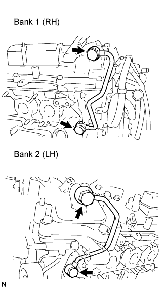 |
Remove the oil pipe No. 1 or No. 2.
Remove the oil control valve filter.
Check that the filter and pipe are not clogged.
- OK:
- Filter is not clogged.
|
| ||||
| OK | |
| 7.REPLACE CAMSHAFT TIMING GEAR ASSEMBLY (FOR EXHAUST CAMSHAFT) |
| NEXT | |
| 8.READ OUTPUT DTC (CHECK IF DTC OUTPUT RECURS) |
Clear the DTCs.
Operate the intelligent tester, or disconnect the EFI and ETCS fuses more than 60 sec. to erase the codes.
Start the engine and warm up the engine.
Switch the ECM from normal mode to check mode using the tester (Click here).
Drive the vehicle for more than 10 minutes or more.
Read output DTCs using the intelligent tester.
- OK:
- No DTC output.
- HINT:
- DTC P0014, P0015, P0024 or P0025 is output when foreign objects in engine oil are caught in some parts of the system. These codes will stay registered even if the system returns to normal after a short time. These foreign objects are then captured by the oil, thus eliminating the source of the problem.
|
| ||||
| NG | ||
| ||