Front Door Window Frame Moulding -- Installation |
- HINT:
- Use the same procedure for the RH and LH sides.
- The procedure listed below is for the LH side.
- When installing the window frame moulding, heat the vehicle body and window frame moulding using a heat light.
- Standard Heating Temperature:
Item Temperature Vehicle Body 40 to 60°C (104 to 140°F) Window Frame Moulding 20 to 30°C (68 to 86°F)
- NOTICE:
- Do not heat the vehicle body and window frame moulding excessively.
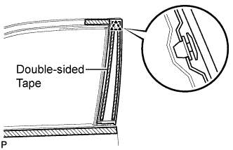
| 1. INSTALL FRONT DOOR REAR WINDOW FRAME MOULDING LH |
Clean the vehicle body surface.
Using a heat light, heat the vehicle body surface.
Remove the double-sided tape from the vehicle body surface.
Wipe off any tape adhesive residue with cleaner.
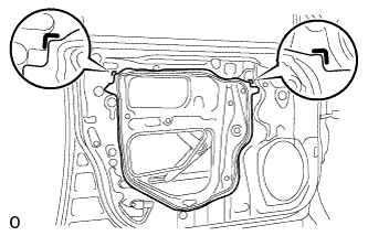
Install a new window frame moulding.
Using a heat light, heat a new window frame moulding and the vehicle body surface.
Remove the peeling paper from the face of the window frame moulding.
- HINT:
- After removing the peeling paper, keep the exposed adhesive free from foreign matter.
Attach the clip and double-sided tape to install the window frame moulding.
- HINT:
- Press the window frame moulding firmly to install it.
| 2. INSTALL FRONT DOOR BELT MOULDING ASSEMBLY LH |
 |
Attach the claw to install the belt moulding.
| 3. INSTALL FRONT DOOR GLASS RUN LH |
Install the front door glass run LH.
| 4. INSTALL FRONT DOOR GLASS SUB-ASSEMBLY LH |
Temporarily install the multiplex network master switch assembly.
Connect the cable to the negative (-) battery terminal.
Move the front door window regulator sub-assembly LH so that the front door glass sub-assembly LH bolts can be seen.
Disconnect the cable from the negative (-) battery terminal.
- CAUTION:
- Wait at least 90 seconds after disconnecting the cable from the negative (-) battery terminal to disable the SRS system.
- If the airbag deploys for any reason, it may cause a serious accident.
- NOTICE:
- When disconnecting the cable, some systems need to be initialized after the cable is reconnected (Click here).
Disconnect the multiplex network master switch assembly.
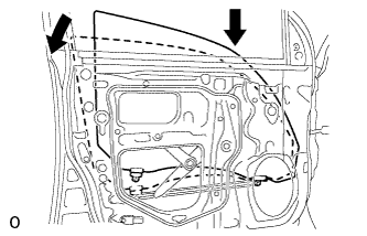
Insert the front door glass sub-assembly LH into the door panel along the glass run as indicated by the arrows in the illustration.
- NOTICE:
- Be careful not to damage the glass.
 |
Install the front door glass sub-assembly LH to the front door window regulator sub-assembly LH with the 2 bolts.
- Torque:
- 8.0 N*m{82 kgf*cm, 71 in.*lbf}
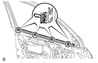
| 5. INSTALL FRONT INNER DOOR GLASS WEATHERSTRIP LH |
Attach the 4 claws to install the front inner door glass weatherstrip LH.
 |
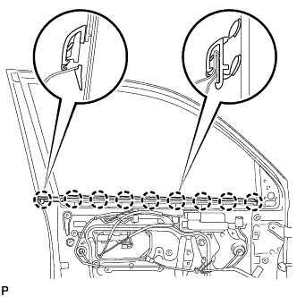
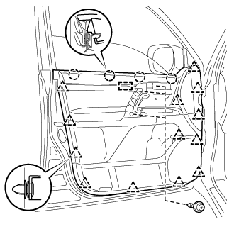
| 6. INSTALL FRONT DOOR SERVICE HOLE COVER LH |
Apply butyl tape to the door.
 |
Pass the front door lock remote control cable assembly LH and front door inside locking cable assembly LH through a new front door service hole cover LH.
- NOTICE:
- When installing the front door service hole cover LH, pull the links and connectors through the front door service hole cover LH.
- There should be no wrinkles or folds after attaching the front door service hole cover LH.
- After attaching the front door service hole cover LH, check the sealing quality.
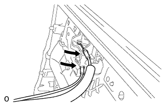
Connect the 2 connectors.
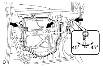 |
Attach the 9 clamps.
Install the bolt as shown in the illustration.
- Torque:
- 8.4 N*m{86 kgf*cm, 74 in.*lbf}
| 7. INSTALL OUTER REAR VIEW MIRROR ASSEMBLY LH |
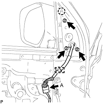 |
Attach the claw and Install the mirror with the 3 nuts.
- Torque:
- 8.0 N*m{82 kgf*cm, 71 in.*lbf}
w/ Power Mirror Control System:
Attach the clamp.
Connect the connector labeled A.
| 8. INSTALL FRONT DOOR TRIM BOARD SUB-ASSEMBLY LH |
Connect the connector.
 |
Connect the front door lock remote control cable assembly LH and front door inside locking cable assembly LH to the front door inside handle sub-assembly LH.
Attach the 4 claws and 13 clips to install the front door trim board sub-assembly LH.
 |
Install the 3 screws.
| 9. INSTALL DOOR ASSIST GRIP COVER LH |
Attach the 8 claws to install the door assist grip cover LH to the front door trim board sub-assembly LH.
| 10. INSTALL FRONT DOOR ARMREST BASE PANEL ASSEMBLY LH |
Connect the connector.
Attach the 5 claws to install the armrest base panel.
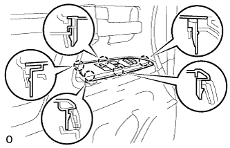 |
| 11. INSTALL FRONT DOOR INSIDE HANDLE BEZEL LH |
Attach the 4 claws to install the front door inside handle bezel LH.
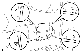 |
| 12. INSTALL FRONT LOWER DOOR FRAME BRACKET GARNISH LH |
Attach the clip and claw, and install the front door lower frame bracket garnish LH.
| 13. CONNECT CABLE TO NEGATIVE BATTERY TERMINAL |
- NOTICE:
- When disconnecting the cable, some systems need to be initialized after the cable is reconnected (Click here).