Land Cruiser URJ200 URJ202 GRJ200 VDJ200 - 1UR-FE FUEL
FUEL INJECTOR - INSTALLATION
| 1. INSTALL FUEL INJECTOR ASSEMBLY |
Attach the 3 clamps to install the No. 6 wire harness to the fuel delivery pipe.
Attach the 3 clamps to install the No. 7 wire harness to the No. 2 fuel delivery pipe.
Apply gasoline or spindle oil to a new O-ring and install the O-ring to the injector.
- NOTICE:
- Make sure that there is no damage or foreign material in the groove of the injector when installing the O-ring.
Connect the injector connector.
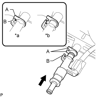
Install the injector to the delivery pipe as shown in the illustration.
| *a | CORRECT |
| *b | INCORRECT |
- NOTICE:
Check that each injector is installed to the delivery pipe facing the direction shown in the illustration.
| *a | Fuel Delivery Pipe |
| *b | No. 2 Fuel Delivery Pipe |
| 2. INSTALL NO. 2 FUEL DELIVERY PIPE SUB-ASSEMBLY |
Install the 2 delivery pipe spacers and 4 insulators to the cylinder head LH.
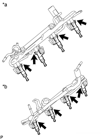
Install the delivery pipe together with the injectors to the cylinder head LH.
Install the 2 bolts.
- Torque:
- 21 N*m{ 214 kgf*cm, 15 ft.*lbf}
- NOTICE:

- Make sure that the part of the injector labeled B is between the parts of the delivery pipe labeled A.
| *1 | Fuel Delivery Pipe |
| *2 | Fuel Injector |
| *a | CORRECT |
| *b | INCORRECT |
Connect the No. 7 wire harness connector.
| 3. INSTALL FUEL DELIVERY PIPE SUB-ASSEMBLY |
Install the 2 delivery pipe spacers and 4 insulators to the cylinder head RH.
Install the delivery pipe together with the injectors to the cylinder head RH.
Install the 2 bolts.
- Torque:
- 21 N*m{ 214 kgf*cm, 15 ft.*lbf}
- NOTICE:
- Make sure that the part of the injector labeled B is between the parts of the delivery pipe labeled A.
| *1 | Fuel Delivery Pipe |
| *2 | Fuel Injector |
| *a | CORRECT |
| *b | INCORRECT |
Connect the No. 6 wire harness connector.
| 4. CONNECT FUEL HOSE |
Connect the fuel hose to the fuel No. 2 fuel delivery pipe ().
Attach the clamp.
| 5. CONNECT WIRE HARNESS AND HOSE |
Connect the purge VSV connector.
Connect the purge line hose to the purge VSV.
Connect the vacuum switching valve connector (for ACIS).
| 6. CONNECT FUEL TUBE SUB-ASSEMBLY |
Connect the fuel tube to the No. 2 fuel delivery pipe ().
Connect the fuel tube to the fuel delivery pipe ().
| 7. CONNECT NO. 2 FUEL TUBE SUB-ASSEMBLY |
Connect the No. 2 fuel tube to the fuel pressure regulator ().
| 8. INSTALL EGR VALVE BRACKET |
Install the EGR valve bracket with the 3 bolts.
- Torque:
- 21 N*m{ 214 kgf*cm, 15 ft.*lbf}
Attach the 2 wire harness clamps and PCV hose clamp.
| 9. INSTALL NO. 5 WATER BY-PASS PIPE |
Install the No. 5 water by-pass pipe with the 2 bolts and connect the 2 water by-pass hoses.
- Torque:
- 21 N*m{ 214 kgf*cm, 15 ft.*lbf}
| 10. INSTALL AIR SWITCHING VALVE ASSEMBLY (w/ Secondary Air Injection System) |
| 11. INSTALL AIR CLEANER CAP AND HOSE |
Install the air cleaner cap and hose, and then tighten the hose clamp.
- Torque:
- 2.5 N*m{ 25 kgf*cm, 22 in.*lbf}
Attach the 4 clamps.
Connect the mass air flow meter connector and attach the clamp.
Connect the No. 2 PCV hose and No. 1 air hose.
| 12. CONNECT CABLE TO NEGATIVE BATTERY TERMINAL |
- NOTICE:
- When disconnecting the cable, some systems need to be initialized after the cable is reconnected ().
| 13. ADD ENGINE COOLANT |
Add engine coolant.
- Standard Capacity (w/o ATF Warmer):
Item Specified Condition w/ Rear Heater 16.5 liters (17.4 US qts, 14.5 Imp. qts) w/o Rear Heater 13.8 liters (14.6 US qts, 12.1 Imp. qts)
- Standard Capacity (w/ ATF Warmer):
Item Specified Condition w/ Rear Heater 17.0 liters (18.0 US qts, 15.0 Imp. qts) w/o Rear Heater 14.2 liters (15.0 US qts, 12.5 Imp. qts)
- NOTICE:
- Do not substitute plain water for engine coolant.
- HINT:
Slowly pour coolant into the radiator reservoir until it reaches the F line.
Install the reservoir cap.
Install the radiator cap.*1
Start the engine and stop it immediately.*2
Allow approximately 10 seconds to pass. Then remove the radiator cap and check the coolant level. If the coolant level has decreased, add coolant.*3
Repeat steps *1, *2 and *3 until the coolant level does not decrease.
- HINT:
- Be sure to perform this step while the engine is cold, as air in the No. 1 radiator hose will flow into the radiator if the engine is warmed up and the thermostat opens.
Install the radiator cap.*4
Set the air conditioning as follows.*5
| Item | Condition |
| Fan speed | Any setting except off |
| Temperature | Toward WARM |
| Air conditioning switch | Off |
Start the engine, warm it up until the thermostat opens, and then continue to run the engine for several minutes to circulate the coolant.*6
- CAUTION:
- NOTICE:
- HINT:
Stop the engine, wait until the engine coolant cools down to ambient temperature. Then remove the radiator cap and check the coolant level.*7
- CAUTION:
- Do not remove the radiator cap while the engine and radiator are still hot. Pressurized, hot engine coolant and steam may be released and cause serious burns.
If the coolant level has decreased, add coolant and warm up the engine until the thermostat opens.*8
If the coolant level has not decreased, check that the coolant level in the radiator reservoir is at the F line.
If the coolant level is below the F line, repeat steps *4 through *8.
If the coolant level is above the F line, drain coolant until the coolant level reaches the F line.
| 14. INSPECT FOR FUEL LEAK |
Make sure that there are no fuel leaks after performing maintenance on the fuel system.
Connect the GTS to the DLC3.
Turn the engine switch on (IG) and turn the GTS on.
- NOTICE:
- Do not start the engine.
Enter the following menus: Powertrain / Engine and ECT / Active Test / Control the Fuel Pump / Speed.
Check that there are no leaks from the fuel system.
If there are fuel leaks, repair or replace parts as necessary.
Turn the engine switch off.
Disconnect the GTS from the DLC3.
| 15. INSPECT FOR COOLANT LEAK |
- CAUTION:
- To avoid being burned, do not remove the radiator reservoir cap while the engine and radiator are still hot. Thermal expansion may cause hot engine coolant and steam to blow out from the radiator.
Remove the radiator cap.
Check for excessive deposits of rust or scales around the radiator reservoir cap and radiator reservoir filler hole. Also, the engine coolant should be free of oil.
If excessively dirty, replace the engine coolant.
Install the radiator cap.
| 16. INSTALL NO. 1 ENGINE UNDER COVER SUB-ASSEMBLY |
Install the No. 1 engine under cover sub-assembly with the 10 bolts.
- Torque:
- 29 N*m{ 296 kgf*cm, 21 ft.*lbf}
| 17. INSTALL FRONT FENDER SPLASH SHIELD SUB-ASSEMBLY LH |
Push in the clip to install the front fender splash shield sub-assembly LH.
Install the 3 bolts and screw.
| 18. INSTALL FRONT FENDER SPLASH SHIELD SUB-ASSEMBLY RH |
Push in the clip to install the front fender splash shield sub-assembly RH.
Install the 3 bolts and 2 screws.
| 19. INSTALL V-BANK COVER SUB-ASSEMBLY |
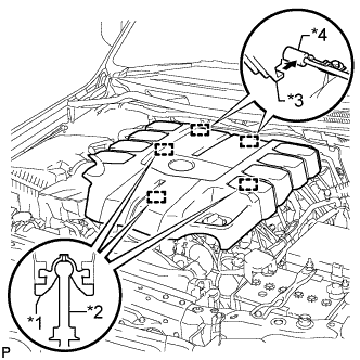
Attach the 2 V-bank cover hooks to the bracket. Then align the 3 V-bank cover grommets with the 3 pins, and press down on the V-bank cover to attach the pins.
| *1 | Grommet |
| *2 | Pin |
| *3 | Hook |
| *4 | Bracket |