Lighting System All Stop Light Do Not Illuminate
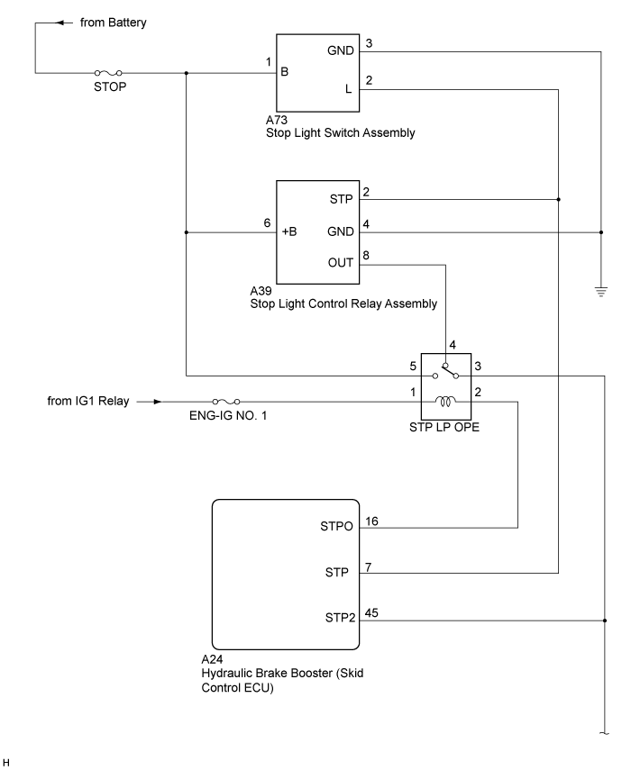
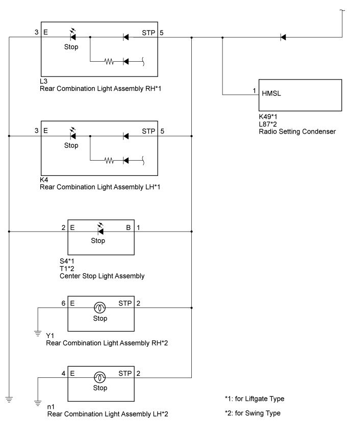
WIRING DIAGRAM
INSPECTION PROCEDURE
CHECK STOP LIGHT OPERATION
CHECK HARNESS AND CONNECTOR (OUT)
CHECK STOP LIGHT CONTROL RELAY ASSEMBLY (OUT)
LIGHTING SYSTEM - ALL Stop Light do not Illuminate |
WIRING DIAGRAM
INSPECTION PROCEDURE
| 1.CHECK STOP LIGHT OPERATION |
Check that the stop lights illuminate when the brake pedal is depressed.
- OK:
- The stop lights illuminate when the brake pedal is depressed.
| OK |
|
|
|
| CHECK CONNECTOR CONNECTION CONDITION |
|
| 2.CHECK HARNESS AND CONNECTOR (OUT) |
Disconnect the A24 hydraulic brake booster (skid control ECU) connector.
Disconnect the A39 stop light control relay connector.
Disconnect the S4 or T1 center stop light assembly connector.
Disconnect the L3 or Y1 rear combination light assembly RH connector.
Disconnect the K4 or n1 rear combination light assembly LH connector.
Disconnect the K49 or L87 radio setting condenser connector.
Measure the resistance according to the value(s) in the table below.
- Standard Resistance:
Tester Connection
| Condition
| Specified Condition
|
A24-45 (STP2) - A39-8 (OUT)
| Always
| Below 1 Ω
|
A24-45 (STP2) - Body ground
| Always
| 10 kΩ or higher
|
| | REPAIR OR REPLACE HARNESS OR CONNECTOR |
|
|
| 3.CHECK STOP LIGHT CONTROL RELAY ASSEMBLY (OUT) |
Disconnect the S4 or T1 center stop light assembly connector.
Disconnect the L3 or Y1 rear combination light assembly RH connector.
Disconnect the K4 or n1 rear combination light assembly LH connector.
Disconnect the K49 or L87 radio setting condenser connector.
Measure the voltage according to the value(s) in the table below.
- Standard Voltage:
Tester Connection
| Condition
| Specified Condition
|
A39-8 (OUT) - Body ground
| Brake pedal depressed
| 11 to 14 V
|
| | REPLACE STOP LIGHT CONTROL RELAY ASSEMBLY |
|
|
| OK |
|
|
|
| REPAIR OR REPLACE REPAIR OR REPLACE CENTER STOP LIGHT ASSEMBLY, REAR COMBINATION LIGHT ASSEMBLY AND RADIO SETTING CONDENSER |
|