Lighting System Engine Switch Illumination Circuit
DESCRIPTION
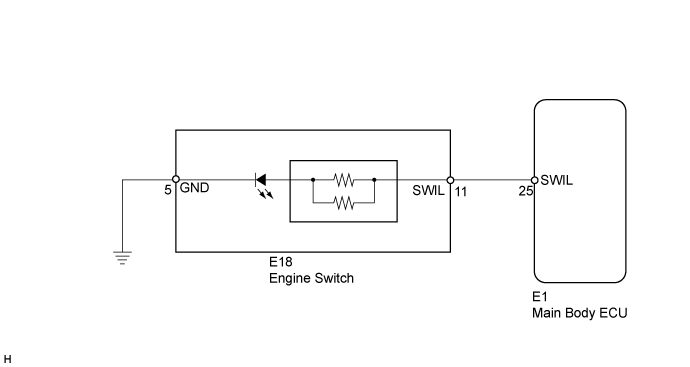
WIRING DIAGRAM
INSPECTION PROCEDURE
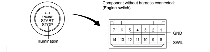
INSPECT ENGINE SWITCH
CHECK HARNESS AND CONNECTOR (ENGINE SWITCH - MAIN BODY ECU AND BODY GROUND)
LIGHTING SYSTEM - Engine Switch Illumination Circuit |
DESCRIPTION
The engine switch illumination is controlled by the main body ECU. The operation and condition of this control are described below (Light control switch is OFF).Operation
| Condition
|
Fade in
| When any of the following conditions is met, the engine switch illumination fades in.
- The key enters any actuation area around the doors when the engine switch is off and all the doors are closed.
- Any door is opened.
- Any door is unlocked when the engine switch is off and all the doors are closed.
- The engine switch is turned from on (ACC) to off when all the doors are closed.
|
Fade out immediately
| When either of the following conditions is met, the engine switch illumination fades out.
- The engine switch is turned from off to on (ACC) or on (IG) when all the doors are closed.
- All the doors are locked when the engine switch is off.
|
Illuminate for approximately 15 seconds, and then fade out
| All the doors are closed when the engine switch is off.
|
WIRING DIAGRAM
INSPECTION PROCEDURE
Remove the engine switch (Click here).
Apply battery voltage to the engine switch.
Check that the illumination comes on.
- OK:
Measurement Condition
| Specified Condition
|
Battery positive (+) → Terminal 11 (SWIL)
Battery negative (-) → Terminal 5 (GND)
| Engine switch illumination comes on
|
| 2.CHECK HARNESS AND CONNECTOR (ENGINE SWITCH - MAIN BODY ECU AND BODY GROUND) |
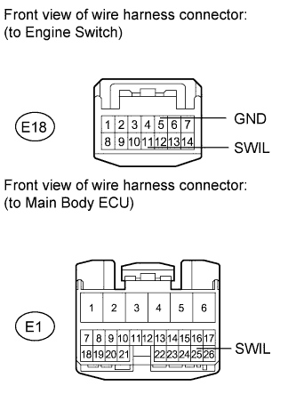
Disconnect the E1 ECU connector.
Disconnect the E18 engine switch connector.
Measure the resistance according to the value(s) in the table below.
- Standard Resistance:
Tester Connection
| Condition
| Specified Condition
|
E1-11 (SWIL) - E1-25 (SWIL)
| Always
| Below 1 Ω
|
E18-5 (GND) - Body ground
|
E1-11 (SWIL) - Body ground
| Always
| 10 kΩ or higher
|
| | REPAIR OR REPLACE HARNESS OR CONNECTOR |
|
|