Lighting System Light Control Switch Circuit
DESCRIPTION
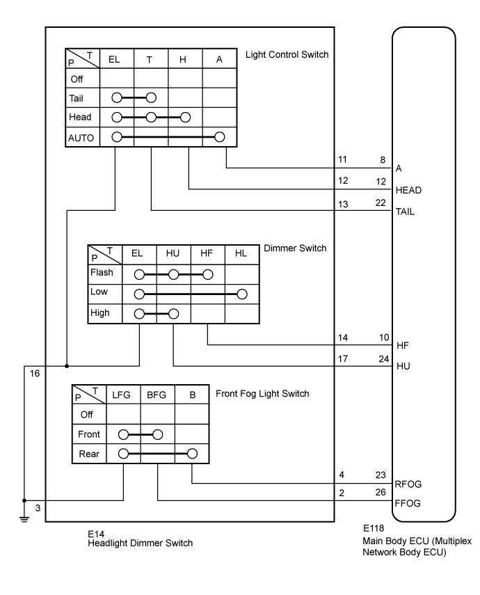
WIRING DIAGRAM
INSPECTION PROCEDURE
READ VALUE USING GTS (HEADLIGHT DIMMER SWITCH)
INSPECT HEADLIGHT DIMMER SWITCH ASSEMBLY
CHECK HARNESS AND CONNECTOR (HEADLIGHT DIMMER SWITCH - MAIN BODY ECU AND BODY GROUND)
LIGHTING SYSTEM - Light Control Switch Circuit |
DESCRIPTION
The main body ECU receives light control switch, dimmer switch and front fog light switch information signals from the headlight dimmer switch.
WIRING DIAGRAM
- for LH side
- for RH side
INSPECTION PROCEDURE
| 1.READ VALUE USING GTS (HEADLIGHT DIMMER SWITCH) |
Operate the GTS according to the display and select the "Data List".
Main BodyTester Display
| Measurement Item/Range
| Normal Condition
| Diagnostic Note
|
Dimmer SW
| Dimmer switch signal/ON or OFF
| ON: Dimmer switch on
OFF: Dimmer switch off
| -
|
Passing Light SW
| Passing light switch signal/ON or OFF
| ON: Passing light switch on
OFF: Passing light switch off
| -
|
Front Fog Light SW
| Front fog light switch signal/ON or OFF
| ON: Front fog light switch on
OFF: Front fog light switch off
| -
|
Rear Fog Light SW
| Rear fog light switch signal/ON or OFF
| ON: Rear fog light switch on
OFF: Rear fog light switch off
| -
|
Auto Light SW
| Auto light switch signal/ON or OFF
| ON: Auto light switch on
OFF: Auto light switch off
| -
|
Head Light SW (Head)
| Headlight switch signal/ON or OFF
| ON: Headlight switch (Head) on
OFF: Headlight switch (Head) off
| -
|
Head Light SW (Tail)
| Taillight switch signal/ON or OFF
| ON: Headlight switch (Tail) on
OFF: Headlight switch (Tail) off
| -
|
- OK:
- When combination light switch operation is performed, the result will be the same as above.
| OK |
|
|
|
| PROCEED TO NEXT CIRCUIT INSPECTION SHOWN IN PROBLEM SYMPTOMS TABLE (Click here) |
|
| 2.INSPECT HEADLIGHT DIMMER SWITCH ASSEMBLY |
Inspect the headlight dimmer switch (Click here).
| | REPLACE HEADLIGHT DIMMER SWITCH ASSEMBLY (Click here) |
|
|
| 3.CHECK HARNESS AND CONNECTOR (HEADLIGHT DIMMER SWITCH - MAIN BODY ECU AND BODY GROUND) |
Disconnect the E14 switch connector.
for LH Side:
Disconnect the E118 ECU connectors.
Measure the resistance according to the value(s) in the table below.
- Standard Resistance:
Tester Connection
| Condition
| Specified Condition
|
E14-9 (BFG) - E118-26 (FFOG)
| Always
| Below 1 Ω
|
E14-7 (B) - E118-23 (RFOG)
|
E14-20 (A) - E118-8 (A)
|
E14-19 (H) - E118-12 (HEAD)
|
E14-18 (T) - E118-22 (TAIL)
|
E14-17 (HF) - E118-10 (HF)
|
E14-14 (HU) - E118-24 (HU)
|
E14-15 (EL) - Body ground
|
E14-8 (LFG) - Body ground
|
E14-9 (BFG) - Body ground
| Always
| 10 kΩ or higher
|
E14-7 (B) - Body ground
|
E14-20 (A) - Body ground
|
E14-19 (H) - Body ground
|
E14-18 (T) - Body ground
|
E14-17 (HF) - Body ground
|
E14-14 (HU) - Body ground
|
for RH Side:
Disconnect the E118 ECU connectors.
Measure the resistance according to the value(s) in the table below.
- Standard Resistance:
Tester Connection
| Condition
| Specified Condition
|
E14-2 (BFG) - E118-26 (FFOG)
| Always
| Below 1 Ω
|
E14-4 (B) - E118-23 (RFOG)
|
E14-11 (A) - E118-8 (A)
|
E14-12 (H) - E118-12 (HEAD)
|
E14-13 (T) - E118-22 (TAIL)
|
E14-14 (HF) - E118-10 (HF)
|
E14-17 (HU) - E118-24 (HU)
|
E14-16 (EL) - Body ground
|
E14-3 (LFG) - Body ground
|
E14-2 (BFG) - Body ground
| Always
| 10 kΩ or higher
|
E14-4 (B) - Body ground
|
E14-11 (A) - Body ground
|
E14-12 (H) - Body ground
|
E14-13 (T) - Body ground
|
E14-14 (HF) - Body ground
|
E14-17 (HU) - Body ground
|
| | REPAIR OR REPLACE HARNESS OR CONNECTOR |
|
|