Lighting System Rear Fog Light Circuit
DESCRIPTION
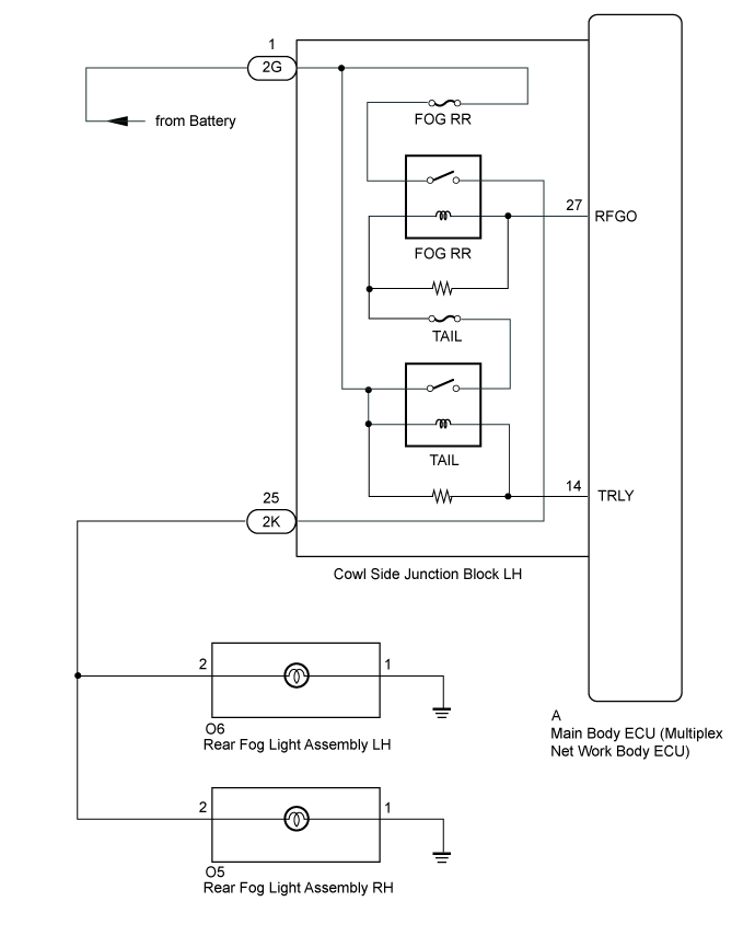
WIRING DIAGRAM
INSPECTION PROCEDURE
PERFORM ACTIVE TEST USING GTS
INSPECT COWL SIDE JUNCTION BLOCK LH
CHECK HARNESS AND CONNECTOR (REAR FOG LIGHT ASSEMBLY - COWL SIDE JUNCTION BLOCK LH)
LIGHTING SYSTEM - Rear Fog Light Circuit |
DESCRIPTION
The main body ECU receives a rear fog light switch information signal from the light control switch (rear fog switch), and illuminates the rear fog lights.
WIRING DIAGRAM
INSPECTION PROCEDURE
| 1.PERFORM ACTIVE TEST USING GTS |
Operate the GTS according to the steps on the display and select "Active Test".
Main BodyTester Display
| Test Part
| Control Range
| Diagnostic Note
|
Rear Fog Light Relay
| Rear fog light
| ON or OFF
| -
|
- OK:
- Fog light turns on/turns off.
ResultResult
| Proceed to
|
OK (for LHD)
| A
|
OK (for RHD)
| B
|
NG
| C
|
| | REPLACE MAIN BODY ECU (MULTIPLEX
NETWORK BODY ECU) (Click here) |
|
|
| |
|
| A |
|
|
|
| REPLACE MAIN BODY ECU (MULTIPLEX
NETWORK BODY ECU) (Click here) |
|
| 2.INSPECT COWL SIDE JUNCTION BLOCK LH |
for LHD
Remove the cowl side junction block LH (Click here).
Remove the main body ECU (multiplex network body ECU) from the cowl side junction block LH (Click here).
for RHD
Remove the cowl side junction block LH (Click here).
Remove the main body ECU (multiplex network body ECU) from the cowl side junction block LH (Click here).
Measure the voltage according to the value(s) in the table below.
- Standard Voltage:
Tester Connection
| Condition
| Specified Condition
|
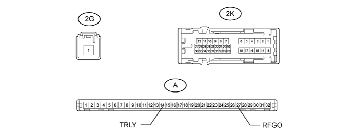
2K-25 - Battery negative (-) terminal
| Battery voltage applied between terminals 2G-1 and A-14 (TRLY) and 2G-1 and A-27 (RFGO)
| 11 to 14 V
|
Battery voltage not applied between terminals 2G-1 and A-14 (TRLY) and 2G-1 and A-27 (RFGO)
| Below 1 V
|
ResultResult
| Proceed to
|
OK
| A
|
NG (for LHD)
| B
|
NG (for RHD)
| C
|
| 3.CHECK HARNESS AND CONNECTOR (REAR FOG LIGHT ASSEMBLY - COWL SIDE JUNCTION BLOCK LH) |
Disconnect the O6*1 and O5*2 rear fog connector.
- *1: for LH
- *2: for RH
Disconnect the 2K junction block connector.
Measure the resistance according to the value(s) in the table below.
- Standard Resistance:
for LHTester Connection
| Condition
| Specified Condition
|
O6-2 - 2K-25
| Always
| Below 1 Ω
|
O6-2 or 2K-25 - Body ground
| Always
| 10 kΩ or higher
|
for RHTester Connection
| Condition
| Specified Condition
|
O5-2 - 2K-25
| Always
| Below 1 Ω
|
O5-2 or 2K-25 - Body ground
| Always
| 10 kΩ or higher
|
ResultResult
| Proceed to
|
OK (for LHD)
| A
|
OK (for RHD)
| B
|
NG
| C
|
| | REPLACE MAIN BODY ECU (MULTIPLEX
NETWORK BODY ECU) (Click here) |
|
|
| | REPAIR OR REPLACE HARNESS OR CONNECTOR |
|
|
| A |
|
|
|
| REPLACE MAIN BODY ECU (MULTIPLEX
NETWORK BODY ECU) (Click here) |
|