Lighting System Drl Relay Circuit
DESCRIPTION
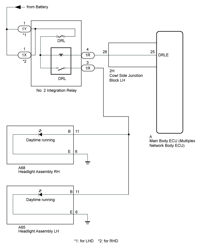
WIRING DIAGRAM
INSPECTION PROCEDURE
PERFORM ACTIVE TEST USING GTS (DAYTIME RUNNING LIGHT)
CHECK HARNESS AND CONNECTOR (NO. 2 INTEGRATION RELAY - BATTERY)
CHECK HARNESS AND CONNECTOR (NO. 2 INTEGRATION RELAY - COWL SIDE JUNCTION BLOCK LH)
INSPECT COWL SIDE JUNCTION BLOCK LH
INSPECT NO.2 INTEGRATION RELAY (DRL RELAY)
CHECK HARNESS AND CONNECTOR (NO. 2 INTEGRATION RELAY - HEADLIGHT ASSEMBLY)
LIGHTING SYSTEM - DRL Relay Circuit |
DESCRIPTION
The LED daylight system illuminates the lights when the light control switch position signal, engine speed signal and surrounding brightness signal are input to the main body ECU (multiplex network body ECU) and the LED daylight system operation conditions are met.
WIRING DIAGRAM
INSPECTION PROCEDURE
- NOTICE:
- Inspect the fuses for circuits related to this system before performing the following inspection procedure.
- Recognition code registration is necessary when replacing the main body ECU (multiplex network body ECU).
- If the main body ECU (multiplex network body ECU) is replaced, refer to the Service Bulletin.
| 1.PERFORM ACTIVE TEST USING GTS (DAYTIME RUNNING LIGHT) |
Using the GTS, perform the Active Test (Click here).
Main BodyTester Display
| Test Part
| Control Range
| Diagnostic Note
|
Daytime Running Light
| DRL light illumination operation
| ON or OFF
| Only when "Daytime Running Light" in the GTS customization settings is set to "ON".
|
- OK:
- Daytime running lights come on.
| OK |
|
|
|
| PROCEED TO NEXT SUSPECTED AREA SHOWN IN PROBLEM SYMPTOMS TABLE (Click here) |
|
| 2.CHECK HARNESS AND CONNECTOR (NO. 2 INTEGRATION RELAY - BATTERY) |
Disconnect the No. 2 integration relay connectors.
Measure the voltage according to the value(s) in the table below.
- Standard Voltage:
for LHDTester Connection
| Condition
| Specified Condition
|
1Y-1 - Body ground
| Always
| 11 to 14 V
|
for RHDTester Connection
| Condition
| Specified Condition
|
1X-1 - Body ground
| Always
| 11 to 14 V
|
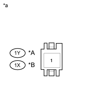
Text in Illustration*A
| for LHD
|
*B
| for RHD
|
*a
| Front view of wire harness connector
(to No. 2 Integration Relay)
|
| | REPAIR OR REPLACE HARNESS OR CONNECTOR |
|
|
| 3.CHECK HARNESS AND CONNECTOR (NO. 2 INTEGRATION RELAY - COWL SIDE JUNCTION BLOCK LH) |
Disconnect the 1R No. 2 integration relay connector.
Disconnect the 2H cowl side junction block LH connector.
Measure the resistance according to the value(s) in the table below.
- Standard Resistance:
Tester Connection
| Condition
| Specified Condition
|
1R-4 - 2H-28
| Always
| Below 1 Ω
|
1R-4 - Body ground
| Always
| 10 kΩ or higher
|
| | REPAIR OR REPLACE HARNESS OR CONNECTOR |
|
|
| 4.INSPECT COWL SIDE JUNCTION BLOCK LH |
for LHD:
- Remove the cowl side junction block LH (Click here).
- Remove the main body ECU from the cowl side junction block LH (Click here).
for RHD:
- Remove the cowl side junction block LH (Click here ).
- Remove the main body ECU from the cowl side junction block LH (Click here).
Measure the resistance according to the value(s) in the table below.
- Standard Resistance:
Tester Connection
| Condition
| Specified Condition
|
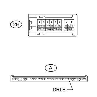
A-25 (DRLE) - 2H-28
| Always
| Below 1 Ω
|
ResultResult
Result | Proceed to
|
OK
| A
|
NG (for LHD)
| B
|
NG (for RHD)
| C
|
| 5.INSPECT NO.2 INTEGRATION RELAY (DRL RELAY) |
Inspect the No. 2 integration relay (Click here).
| | REPLACE NO.2 INTEGRATION RELAY |
|
|
| 6.CHECK HARNESS AND CONNECTOR (NO. 2 INTEGRATION RELAY - HEADLIGHT ASSEMBLY) |
Disconnect the 1R No. 2 integration relay connector.
Disconnect the A68 headlight assembly LH connector.
Disconnect the A65 headlight assembly RH connector.
Measure the resistance according to the value(s) in the table below.
- Standard Resistance:
Tester Connection
| Condition
| Specified Condition
|
1R-3 - A65-11(B)
| Always
| Below 1 Ω
|
1R-3 - A68-11(B)
| Always
| Below 1 Ω
|
1R-3 - Body ground
| Always
| 10 kΩ or higher
|
ResultResult
Result | Proceed to
|
OK (for LHD)
| A
|
NG
| B
|
OK (for RHD)
| C
|
| | REPAIR OR REPLACE HARNESS OR CONNECTOR |
|
|
| | REPLACE MAIN BODY ECU (MULTIPLEX NETWORK BODY ECU) (Click here) |
|
|
| A |
|
|
|
| REPLACE MAIN BODY ECU (MULTIPLEX NETWORK BODY ECU) (Click here) |
|